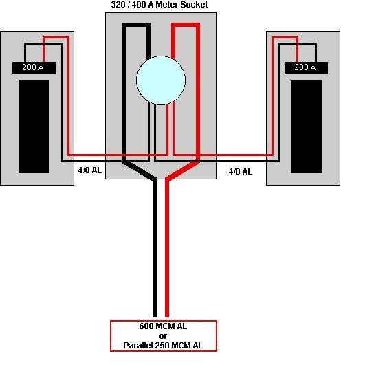
No neutral to panel supplying 240v-only loads, right?

Status
Not open for further replies.
My confusion was that larry posted nearly identical reply to what is quoted in this post in another thread, and I thought I was reading that thread. Sorry about that.
Actually, I copied the post to that other thread because it pertained to the same job.
 
When paralleling two conductors together you have what is defined as a single conductor do you not, so where does the NEC say two conductors 1/0 and larger cannot be paralleled to form a single conductor?

I'm unsure we're discussing the same thing but in 250.66 there are minimum sizes for GEC's. There is nothing in that section that allows you to use two smaller conductors to make one big one. Also conductors in parallel are generally limited to the types listed in 310.15(H).

310.15(H) Conductors in Parallel.
(1) General. Aluminum, copper-clad aluminum, or copper
conductors, for each phase, polarity, neutral, or grounded
circuit shall be permitted to be connected in parallel
(elec-
trically joined at both ends) only in sizes 1/0 AWG and
larger where installed in accordance with 310.10(H)(2)
through (H)(6).
 
I'm unsure we're discussing the same thing but in 250.66 there are minimum sizes for GEC's. There is nothing in that section that allows you to use two smaller conductors to make one big one. Also conductors in parallel are generally limited to the types listed in 310.15(H).

You are correct main bonding jumpers , grounding electrode conductors , equipment grounds are not listed in that section

so you are saying 2000 anp CT metered service , 600 MCM x 5 = 3000 MCM X 12 1/2 % (375 MCM min. main bonding junper) has to be used. Cannot parallel two smaller conductors to equal the min 375 MCM to bond the neutral to the CT cabinet.

I will have to give that some thought as you said they are not listed in that code section
 
Before we get to far of topic here

what I was trying to say was you cannot use two # 4 awg GEC one from200 amp panel A and a second from the 200 amp service disconnect if a larger common GEC is required for two panels grouped at one location

Second thing that I said the size of the common GEC for two sets of 4/0 Alum service entrance cables for two 200 amp disconnects (service equipment enclosures) would be based on the largest ungrounded service entrance conductor in this case a # 4 awg copper GEC

So the unspliced common grounding electrode conductor size is # 4 already installed from panel 1 in this discussion. So panel 2 only has to tap the existing # 4 GEC already installed from panel 1 with the required #4 GEC Tap
 
I almost forgot to update this. Had my inspection yesterday. The inspector said that I had to use SER instead of SE for the feeder, even though the loads are only line-to-line. I explained that the neutral could stop at the exterior disconnect, but he said that, because it's a feeder, the neutral had to be run to the interior panel. I told him I would consult the code and get back to him.

He said that he's never heard of a feeder without a neutral in 20+ years of inspecting and agreed to call the head inspector (whom I know) for his opinion. The head inspector agreed with the inspector, and also never heard of a feeder with no neutral. As the inspector was typing the failure on his laptop, the head inspector called back and said that I was correct. That made my day!

Glad to hear it went well :)


BTW, one request- can you take some pics? If its to late, never mind.
 
Cool.

Docs320Ametersocket.jpg


P1 is left one, #4 to water and #6 to rods. Existing.

P2 is new. 4/0 SE, #6 to #6 from P1-split bolt.

For P2 easiest for water is just a new #4 to water pipe, otherwise you would have attach both #4 to a GEC sized to 600 kcmil main service conductors and use irreversible connections.

Please help me understand the 4/0 SEU being allowed to the disconnects. I thought if the entire load of the dwelling was not served by one disconnect that you needed to use a fully rated conductor (250mcm AL).
NEC 2014 310.15(B)7(1-4)
 
Please help me understand the 4/0 SEU being allowed to the disconnects. I thought if the entire load of the dwelling was not served by one disconnect that you needed to use a fully rated conductor (250mcm AL).
NEC 2014 310.15(B)7(1-4)
4/0 AL ampacity is 180 amps. As long as the calculated load is not over 180 amps you are permitted to protect it at the next higher standard size overcurrent device which is 200 amps.
 
Please help me understand the 4/0 SEU being allowed to the disconnects. I thought if the entire load of the dwelling was not served by one disconnect that you needed to use a fully rated conductor (250mcm AL).
NEC 2014 310.15(B)7(1-4)

4/0 AL ampacity is 180 amps. As long as the calculated load is not over 180 amps you are permitted to protect it at the next higher standard size overcurrent device which is 200 amps.

And the new panel has a calculated load of 160A.

The old panel has less of a load because it no longer has a HW circuit load.

The existing and new 4/0 AL works fine.
 
Please help me understand the 4/0 SEU being allowed to the disconnects. I thought if the entire load of the dwelling was not served by one disconnect that you needed to use a fully rated conductor (250mcm AL).
NEC 2014 310.15(B)7(1-4)

You are correct that you cannot use the 83% rule but you can use the next size up rule which in this example gives you the same conductor size.
 
Status
Not open for further replies.
Top