Odd question for neutral connection

Status
Not open for further replies.

LarryFine

Master Electrician Electric Contractor Richmond VA
Location
Henrico County, VA
Occupation
Electrical Contractor
Okay, to answer your first question, no, the source neutral should not be used as a bonding conductor for your output.

I'm still interested in why you're asking. In other words, why do you think it either should or should not be connected?

Are you looking to use low voltage wiring to transmit 120v? How long would your 24v circuit be if it becomes a installed?
 

oldsparky52

Senior Member
You stopped the common conductor right after the Variac transformer. The theoretical transformer is drawn like a resistor in the circuit.

The common conductor needs to connect to the common of the 2nd autotransformer along with the 24V leg, then the common continues to the load along with the 120V lead from the 2nd autotransformer. You do not have it drawn that way, and I'm talking autotransformers not isolation transformers.
 
Location
Texas
Occupation
Electrician
I see your logic and the original post where I said the.second one was also an autotransformer, I didnt understand the implications by saying that.
 

LarryFine

Master Electrician Electric Contractor Richmond VA
Location
Henrico County, VA
Occupation
Electrical Contractor
Now we get your question! The two wires coming from the Variac need to connect to the two wires on the "24v" side of your experimental transformer. Presuming you're using real disconnects, there should be a terminal bar for the neutral in each one.

You would connect the wire from the variable output of the auto-transformer to the line hot terminal of your first disconnect, and for the wire you have not connected to anything yet, connect it to the neutral bar in the disco. From the load hot terminal of your first disconnect, you would run one wire to one 24v transformer terminal, and from the same neutral bar, you would run a wire to the other terminal of your 24v transformer. That completes one circuit.

The 120v output wires of your new transformer would feed the second disconnect the same way: one wire to the line hot, one wire to the neutral bar, one wire from the load hot to your new load, and one wire from the neutral bar to your new load. Your new 120v output circuit is isolated from the source IF there is absolutely no connection between the 24v primary and the 120v secondary. That means it's a separately-derived system.

What I thought you had been asking was whether any of the new 120v wires should be connected to the supply neutral. The answer is no. If it's an SDS, it should be connected to a grounding electrode system of some kind, unless this is never going to be installed as an actual part of a premises system. Do keep in mind that, for every amp at 120v used at the load, there will be (120 / 24) 5 amps in the 24v portion of the circuit.
 

LarryFine

Master Electrician Electric Contractor Richmond VA
Location
Henrico County, VA
Occupation
Electrical Contractor
For info:

In this example, the auto-transformer is shown as step-up; in your use, reverse the input and output designations.

1581380577371.jpeg


Found another one:

main-qimg-2f810c218ff19e863d3c3ab4220f7042.webp


images
 
Last edited:

gar

Senior Member
Location
Ann Arbor, Michigan
Occupation
EE
200212-1151 EST

Travis:

I believe your goal is to run an experiment on an experimental transformer of your own making.

From the discussion so far I don't believe you have had either a high school chemistry or physics class. In either case you would have learned how to define. describe, do, and report on an experiment.

You have not defined your experiment.

A formal physics experiment and report would consist of the following parts:

1. Purpose --- here you define what is the purpose of the experiment. As an example --- how does the v-i curve of a 1N4148 diode vary as a function of ambient air temperature in a horizontal position with no forced air cooling?

2. Equipment --- a list of everything needed. For example --- a temperature chamber of adequate size, a means to change temperature, a thermometer, a voltmeter, a milliammeter, a means to adjust a steady current, and pencil and paper.

3. Procedure --- how to perform the experiment.

4. Data from running the experiment.

5. Conclusions.

You may do much of the above in your head. But you have told us virtually nothing about the experiment. Initially you said the item to be tested was an autotransformer. But later I think you changed it to an isolation transformer, but not using the term isolation.

You have not told us what you want to learn about the transformer under test. That means we have no ides what will be connected to the transformer as a load or test equipment.

What you have done is get all hung up on NEC rules. That is just noise, or instrumentation problems to your experiment.

You need an insulated table on which to locate your transformer under test, and other components of the test.

Apparently you want an AC 60 Hz sine wave voltage source as the input to your experiment. For this you are using a Variac. Does it need to be adjustable in amplitude? I expect it should be. What do you need as a source impedance? Does the source need to be isolated? I would like it to be, but when i run experiments I tend to work around that problem other ways.

You are hung up on NEC rules, and you don't have some clear definitions of words, and electrical circuit theory.

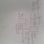
Forget the NEC stuff for the moment, and tell us about the experiment. Then we can work around NEC later. For the moment assume you have an isolated adjustable AC sine wave source. This is drawn on a diagram as a circle with a single cycle sine wave in the middle, one wire from the top, and one from the bottom.

What type of instruments are used on the load will determine the need for isolation of the input power, or how to work around a non-isolated source.

.
 
Status
Not open for further replies.
Top