Old Roth Brothers and Company motor on a jewelry metal rolling machine.

Status
Not open for further replies.

Brue

Member
The machine dates from about 1895 to 1905. I'm attempting to attach a picture of the motor name plate. The motor has six unmarked leads. I have an ohm map between them and to motor frame.
imagejpeg
 

Attachments

  • image.jpg
    image.jpg
    23.5 KB · Views: 3
View attachment 23227
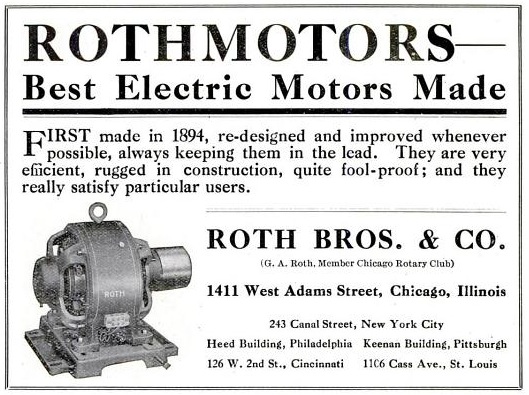
If you can expand this photo you will see that the motor isn't as old as the one in the ad.

Is that thing direct or belt driven? If it's belt and there isn't a need to keep it original the best thing to do is replace the motor.

If they wish to keep the machine in original condition check and see if there is a motor shop that will do a rewind and rebuild. They will mark those leads for you.
 
1 HP
230 V
4-5 >> .74 ohms
2-3 >> 38.5 ohms
1-6 >> open
1200 rpm - that's odd. An induction motor would be maybe 1185 rpm. 1 hp is really small for a synchronos motor and it is not three phase. Maybe listing the synchronous speed was the norm for that time.

No chance of finding the controller?

Without the controller, I'm guessing:
1 phase
4-5 run winding
2-3 start winding
1-6 centrifugal switch stuck open
Capacitor was in the controller.


And I'm thinking you already figured out to head to a motor shop..
 
Minor thought:
If 1-6 is a stuck open switch, they probably started it by giving the pulley a flip in the appropriate dirction.

If so, you could make a test:
Remove the belt.

With your favorite helper standing by the ON-OFF switch/plug and cord connection
Connect 4-5 to 120V.
Give the motor pulley a flip.
See if it takes off and runs. It won't have much power, but it should run unloaded.

Interesting, relative low risk science fair project
 
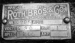
I can read the table.

Was the machine working? Is it new to this owner? No name plate mark to indicate single or three phase. Any idea? Is there a thermal reset button? Is there a capacitor mounted to motor?

Does it smell burned?

Hey, thanks for responding.
It is new to this owner. It's unknown if it was working. The electrical box cover on the motor is missing, it may have contained a capacitor. No name plate indication of single or three phase. I did not see a reset button. There is no capacitor mounted to the external surface of the motor. There is zero burnt motor smell. The motor leads show no signs of damage. None of the motor leads test as a shorted connection to the frame of the motor. There is really no sign I can read as indicating a bad motor.
Normally I would just disassemble the motor and inspect it for a centrifugal switch. But the gear chain starts with a small motor shaft gear driving a large gear mounted on a shaft who's bearings are bolted to the top of the motor. The owner was a bit nervous about pulling it all apart. The two wires that I randomly marked 1 and 6 are smaller than the other four.
Aside from hoping someone has worked on a motor with a similar name plate the most basic question I can ask is about the two Ohmages I measured: do the numbers represent a typical ratio between a start winding and a run winding?
There is another interesting thing: the leads of the 38.6 Ohm winding when tested to the frame of the motor start at about 80 Ohms and build to about 150 Ohms over a ten second time period. Like charging an RC or LC circuit.
 
When did they start labeling motors as 'three phase'? Were AC motors ever just assumed to be Tesla wound? If this were a three phase motor I would expect to find three windings of about equal Omage.

Could the small wires, 1 and 2, just be raw connections to a normally open centrifugal switch or to a damaged normally closed one?
 
There is another interesting thing: the leads of the 38.6 Ohm winding when tested to the frame of the motor start at about 80 Ohms and build to about 150 Ohms over a ten second time period. Like charging an RC or LC circuit.

That behavior sounds more like a capacitor where the current will decrease as the cap voltage gets closer to the thevenin equivalent source voltage of the ohmmeter itself, because I=CdV/dt. The decreasing current and increasing voltage will make the measured resistance R=V/I go up at least initially until it reaches a steady state value equal to the actual ohmic resistance.


By contrast, the current in an inductor will increase with time because V=LdI/dt. Therefore the measured resistance R=V/I will go down at least initially until it reaches the series ohmic resistance of the inductor.
 
image.jpg
This old book from 1924 has helped me identify the leads someone hack sawed off of a WWII Arboga gear head drill press I picked up for $100. I've got it out again.
 
1 HP
230 V
4-5 >> .74 ohms
2-3 >> 38.5 ohms
1-6 >> open
1200 rpm - that's odd. An induction motor would be maybe 1185 rpm. 1 hp is really small for a synchronos motor and it is not three phase. Maybe listing the synchronous speed was the norm for that time.

No chance of finding the controller?

Without the controller, I'm guessing:
1 phase
4-5 run winding
2-3 start winding
1-6 centrifugal switch stuck open
Capacitor was in the controller.


And I'm thinking you already figured out to head to a motor shop..


The machine with all its gears weighs 800 pounds. The motor shop would charge to pull the motor out in order to open it up. And they may well damage the gears or their shafts in the process. So I may propose to the owner that I open it up in his shop and take a look expecting to find a centrifugal switch which might be repairable.

if this works do you have a method of sizing a capacitor?
 
Is that thing direct or belt driven? If it's belt and there isn't a need to keep it original the best thing to do is replace the motor.

If they wish to keep the machine in original condition check and see if there is a motor shop that will do a rewind and rebuild. They will mark those leads for you.


It's a gear train with the first stage of reduction bolted to the top of the motor. Very nice castings. But probably dried up oil. Getting the gears lined up upon reassemble could be interesting.
 
It's a gear train with the first stage of reduction bolted to the top of the motor. Very nice castings. But probably dried up oil. Getting the gears lined up upon reassemble could be interesting.

To clean up the old oil/grease, take it to a spray-it-yourself car wash, and hose the whole thing down. Gets all the grease &c out of the works. Rinse thoroughly; re-lube when dry.

Did this with the drum from a 2nd-hand mimeograph machine-- gets all the old ink out, ready for re-use.
 
That behavior sounds more like a capacitor where the current will decrease as the cap voltage gets closer to the thevenin equivalent source voltage of the ohmmeter itself, because I=CdV/dt. The decreasing current and increasing voltage will make the measured resistance R=V/I go up at least initially until it reaches a steady state value equal to the actual ohmic resistance.


By contrast, the current in an inductor will increase with time because V=LdI/dt. Therefore the measured resistance R=V/I will go down at least initially until it reaches the series ohmic resistance of the inductor.

Thanks for that, I'll attempt to file it in my head for future reference. So would this indicate that there is in fact a capacitor inside the motor casing?
 
Thanks for that, I'll attempt to file it in my head for future reference. So would this indicate that there is in fact a capacitor inside the motor casing?

Please note that this behavior was from lead 1 to ground and likewise lead 6 to ground but not so much between leads 1 and 2. Does that flag a problem?
 
Shouldn't be any continuity from any lead to ground. So, yes that looks like a problem.

Your pictures are way too small to determine anything. How about some that are large and that show the motor from different angles? What you posted is mostly of the machine and you can hardly see the motor on the bottom.

-Hal

That's what I thought. Perhaps the centrifugal switch has flung apart and it's not in the windings. I guess the thing needs disassembly.

Yes, I know, I'm new to forums and still figuring out how to do that. Plus it will be July 8 before I can get another look at the machine.
 
Last edited:
Status
Not open for further replies.
Top