Old school relay help

Learn the NEC with Mike Holt now!

Pat75

Member
Location
Maryland
Occupation
Electrician
Hi. I'm working on an old low voltage lighting control system. It has about 45 or so Leviton 24v GE RR7 relays mixed with P&S 1070B relays.
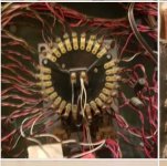
But adjacent to the panel housing the relays are 2 enclosures, each with a round multi pole (probably 50) relay. I'll try to attach the picture.
The enclosures are marked Master relay 1 and master relay 2. I've never seen one like these before. Any one have experience on these?
I'm fine with rr7 and 1070B, just don't see the need for these Masters unless its used for ALL OFF or ALL ON ?

Pictures won't load....
 

hbiss

EC, Westchester, New York NEC: 2014
Location
Hawthorne, New York NEC: 2014
Occupation
EC
Those are stepper relays. Hit the coil and it will advance one position. Likely it is wired to control each location that is controlled by a local button from a central or remote location.

-Hal
 

Pat75

Member
Location
Maryland
Occupation
Electrician
Thanks Hal. I understand a stepper but in this scenario I don't understand why a control scheme would want to step through the control of nearly 50 relays to energize just 1....mean while individually energizing relays that don't need to be energized in the process.
 

gar

Senior Member
Location
Ann Arbor, Michigan
Occupation
EE
230613-1145 EDT

Pat75:

The GE RR relay system uses low voltage coil relays to control a SPST high current 120/240 V bistable switch. The actual switch is a bistable snap blade. There are two relay coils in each relay. One coil is the set coil and the other a reset coil. These relays were never designed for continuous coil excitation.

I never saw or worked with the rotary switch you show. I believe what you show was a master switch to sequentially turn on or off many RR relays. I believe this would be a motor driven switch.

Why would one want such a switch? Each relay coil requires a substantial amount of current to change state. If you switch a large number of relays at once, then the controlling source has to supply a large amount of current all at once. One relay at a time only requires the current capability for one relay at a time for all the components. In addition to this problem is the need to not directly parallel the relay coils. Thus, direct parallel operation would require a diode in each coil path.

The GE RR relay system is a very useful method of switching. My home is all GE RR relays, and these have been working very well since 1965.

..
 

letgomywago

Senior Member
Location
Washington state and Oregon coast
Occupation
residential electrician
230613-1145 EDT

Pat75:

The GE RR relay system uses low voltage coil relays to control a SPST high current 120/240 V bistable switch. The actual switch is a bistable snap blade. There are two relay coils in each relay. One coil is the set coil and the other a reset coil. These relays were never designed for continuous coil excitation.

I never saw or worked with the rotary switch you show. I believe what you show was a master switch to sequentially turn on or off many RR relays. I believe this would be a motor driven switch.

Why would one want such a switch? Each relay coil requires a substantial amount of current to change state. If you switch a large number of relays at once, then the controlling source has to supply a large amount of current all at once. One relay at a time only requires the current capability for one relay at a time for all the components. In addition to this problem is the need to not directly parallel the relay coils. Thus, direct parallel operation would require a diode in each coil path.

The GE RR relay system is a very useful method of switching. My home is all GE RR relays, and these have been working very well since 1965.

..
I've done some repairs and remodels using this system biggest downside was when people wanted normal dimmers and had to have the switch leg redone. Now I'd be tempted to sell them smart trims and bulbs and then they could keep the 60s vibe continuous
 

LarryFine

Master Electrician Electric Contractor Richmond VA
Location
Henrico County, VA
Occupation
Electrical Contractor
They also had systems with manual rotary switches, so one pair of buttons could turn on or off any one light (or group) out of a large number at a time. I seem to recall the rotary knob also being the push button.
 

letgomywago

Senior Member
Location
Washington state and Oregon coast
Occupation
residential electrician
They also had systems with manual rotary switches, so one pair of buttons could turn on or off any one light (or group) out of a large number at a time.
Never saw those just the standard push button with bell wire. Sounds cool but now we have 0-10 do the same thing I wonder if a system like that would be worth it when doing any remodels in a house full of this stuff since it's free from the relays
 

gar

Senior Member
Location
Ann Arbor, Michigan
Occupation
EE
230614-0915 EDT

The RR relay system was never inexpensive, but it was extremely reliable when done in an intelligent fashion.

It was not a problem with loss of power, it retained its last set state. Line voltage transients, such as lightning, did not usually destroy components.

It had good logic capabilities. Any number of switches could be paralleled. Controlling switches were SPDT with spring return to a mid position. UP on any switch could be ON, and DOWN could be OFF. Lighted switches were available so that without being in a location where the load could be seen you could know the state of that circuit.

One switch could control many different loads. All sorts of different combinations could control different circuits.many different ways.

. .
 

AlbertL57

Member
Location
Falls Church, VA
Occupation
Solar maintainer
I think what you have is called a "motor master" switch. It's essentially a rotary switch driven by a motor. Its purpose is to allow a single switch to control multiple relays (by turning on the motor), while still allowing the relays to be operated individually by separate switches.
 

Jraef

Moderator, OTD
Staff member
Location
San Francisco Bay Area, CA, USA
Occupation
Electrical Engineer
I’ve only seen one of these stepper relays used in an older high rise building. As I recall, they used it to avoid a high inrush from turning in all the lights at once. So in the morning, the custodian hit the On button, which engaged the stepper which turned on banks of the RRs, sequentially. In the case I saw it was for floors of the 40 story building. You hit the button, it turned on floors 1, 5, 10, etc, then the next pulse turned on floors 2, 6, 11, on down the line.
 

AlbertL57

Member
Location
Falls Church, VA
Occupation
Solar maintainer
They also had systems with manual rotary switches, so one pair of buttons could turn on or off any one light (or group) out of a large number at a time. I seem to recall the rotary knob also being the push button.
Yes, that's correct. There was a very cool master control station with two 12-position rotary switches - one for ON and one for OFF. To operate an individual relay, you'd turn the ON or OFF knob to the corresponding relay number (there was a lighted directory above) and push it in. Or, a "power user" could hold the knob in while turning it, to operate a series of relays in one motion. The motor master switch pictured in an earlier post is a motor-driven version of that device.
 

AlbertL57

Member
Location
Falls Church, VA
Occupation
Solar maintainer
230614-0915 EDT

The RR relay system was never inexpensive, but it was extremely reliable when done in an intelligent fashion.

It was not a problem with loss of power, it retained its last set state. Line voltage transients, such as lightning, did not usually destroy components.

It had good logic capabilities. Any number of switches could be paralleled. Controlling switches were SPDT with spring return to a mid position. UP on any switch could be ON, and DOWN could be OFF. Lighted switches were available so that without being in a location where the load could be seen you could know the state of that circuit.

One switch could control many different loads. All sorts of different combinations could control different circuits.many different ways.

. .
I've been interested in the RR system for a long time - I actually came across it when I was little, looking through an Audel's electrical book that had a chapter on the system. I liked anything with a lot of wires (still do!), so it obviously caught my attention. I thought it would be fun to have one in my house. And now, years later, I do! My house is small, but I installed a 12-relay system and will expand it when I have time. The relays are in a central enclosure, and are driven by a PLC that all the switches are connected to, so modifications and adding features are easy.

There used to be a Yahoo group devoted to the RR system and competitors. The members were mostly homeowners, many of whom had become very knowledgeable about the systems (of necessity, given the lack of electricians willing and able to work on them), and were committed to preserving and maintaining their installations. That can be challenging even for an pro, because of the often-sloppy practices in the inital installations and modifications, including a lack of labeling for all those wires!
 
Top