Parallel Conductors

Status
Not open for further replies.

69gp

Senior Member
Location
MA
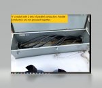
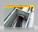
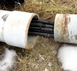
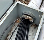
Got a quick question about parallel conductors. I know the the general rules same size conductors all terminated the same on the ends. Came across a job today where there was one 4" PVC conduit with 2-sets of 350 MCM copper plus 2- 2/0 copper for a neutral and one 6" PVC conduit with 2-sets of 350 MCM copper plus 2- 2/0 copper for a neutral. This is about an 800' run on a landfill cap. MV transformer at the base of the hill and terminating at a 1000 Amp panelboard on top. Is this legal per the code? I cannot see how the conductors can be grouped together within the conduits. Also there are several boxes along the way where the conductors are not grouped.

Any input would be appreciated.
 

Attachments

  • parallel conduits..jpg
    parallel conduits..jpg
    185.7 KB · Views: 61
  • 4pa.jpg
    4pa.jpg
    88.5 KB · Views: 61
  • 6inch conduit.jpg
    6inch conduit.jpg
    113.2 KB · Views: 62

LarryFine

Master Electrician Electric Contractor Richmond VA
Location
Henrico County, VA
Occupation
Electrical Contractor
From what you described, the conductor groups are identical, and the only difference is the two conduits are of different size.

Since they're PVC, I don't think that will make an impedance difference. Did I miss another difference?
 

texie

Senior Member
Location
Fort Collins, Colorado
Occupation
Electrician, Contractor, Inspector
A bit unusual but I think Larry is right in that both raceways are PVC and probably won't matter. But I would want to know if those pull boxes are installed at the same points along the route for both conduits. Also those bonding bushings are interesting. Are those pull boxes properly bonded? And of course the PVC run along the surface of the ground is an issue. And the ampacity looks shy by 8 amps. And is there a properly sized EGC (s)?
 

69gp

Senior Member
Location
MA
I have always understood that each group of parallel conductors needs to be grouped together even when they pass through a junction box. My feeling leads me to say that since 2 sets of conductors are in a conduit they cannot be grouped properly.
 

69gp

Senior Member
Location
MA
A bit unusual but I think Larry is right in that both raceways are PVC and probably won't matter. But I would want to know if those pull boxes are installed at the same points along the route for both conduits. Also those bonding bushings are interesting. Are those pull boxes properly bonded? And of course the PVC run along the surface of the ground is an issue. And the ampacity looks shy by 8 amps. And is there a properly sized EGC (s)?
yes there is a ground lug bolted to the box
 

texie

Senior Member
Location
Fort Collins, Colorado
Occupation
Electrician, Contractor, Inspector
yes there is a ground lug bolted to the box
Is there an OCPD at the supply end? If so it needs separate EGCs in addition to the neutrals. If these are service conductors or outside transformer feeders they could use the neutrals for the EGCs but they would all would have to attached to the pull boxes.
 

winnie

Senior Member
Location
Springfield, MA, USA
Occupation
Electric motor research
The basic requirement is that each conductor in parallel have the same characteristics.

This means that all the conductors that make up phase A have to be the same gauge, the same conductor material, the same length, in matching raceways, in the same relation to the other phases, terminated the same way, and arguably the same insulation type. Similarly for the other phases and the neutral. Note that the phases don't have to be the same as each other, eg phase A could be copper and phase B aluminium, or phase C could be different gauge, etc.

You can have multiple parallel sets in the same raceway, say 2 phase A, 2 phase B, 2 phase C, 1 neutral, or some other such arrangement.

If the conductors in a given conduit are not arranged so that parallel conductors al have the same mechanical relation to other phases then arguably there is a violation since the inductance of the different conductors that should be the same is likely different. However this is also a very small effect and probably one that should be ignored.

If you are concerned about this particular installation, take current readings on the individual conductors of the parallel set, and see how different they are. The intent of the code is to get all parallel conductors to share the current evenly.

Jon
 

vsnryele603

New User
Location
Southern NH
Occupation
Electrical Contractor
I mostly work on houses. I noticed this thread. Correct me if i am wrong. The only marking I would think would have to be done is either black, brown, orange, yellow, grey & green. Also you need bonding bushings on pvc. I assume there is correct expansion couplings and it is schedule 80. amperage after de-rating should be 980 amps which allows for a 1000 amp service
 

tom baker

First Chief Moderator & NEC Expert
Staff member
Location
Bremerton, Washington
Occupation
Master Electrician
I mostly work on houses. I noticed this thread. Correct me if i am wrong. The only marking I would think would have to be done is either black, brown, orange, yellow, grey & green. Also you need bonding bushings on pvc. I assume there is correct expansion couplings and it is schedule 80. amperage after de-rating should be 980 amps which allows for a 1000 amp service
What is the reason for bonding bushings on PVC?
Please post the code section that allows conductors rated at 980 amps for the 1000 amp service.
 

Carultch

Senior Member
Location
Massachusetts
What is the reason for bonding bushings on PVC?

Bonding bushings on PVC? Sounds like a defeated purpose of the component.

Maybe the installer didn't have any ordinary plastic bushings, and is just using them in place of plastic bushings for the requirement for bushings in general.
 

69gp

Senior Member
Location
MA
The basic requirement is that each conductor in parallel have the same characteristics.

This means that all the conductors that make up phase A have to be the same gauge, the same conductor material, the same length, in matching raceways, in the same relation to the other phases, terminated the same way, and arguably the same insulation type. Similarly for the other phases and the neutral. Note that the phases don't have to be the same as each other, eg phase A could be copper and phase B aluminium, or phase C could be different gauge, etc.

You can have multiple parallel sets in the same raceway, say 2 phase A, 2 phase B, 2 phase C, 1 neutral, or some other such arrangement.

If the conductors in a given conduit are not arranged so that parallel conductors al have the same mechanical relation to other phases then arguably there is a violation since the inductance of the different conductors that should be the same is likely different. However this is also a very small effect and probably one that should be ignored.

If you are concerned about this particular installation, take current readings on the individual conductors of the parallel set, and see how different they are. The intent of the code is to get all parallel conductors to share the current evenly.

Jon
 

69gp

Senior Member
Location
MA
Unable to take current readings as the conductors are damaged. That means pulling in new conductors. I was unsure of how the paralleling of the wires were laid out within the conduits as they would not really be bundled the same way. In the 6" conduit the conductors lay mostly lin as flat ribbon configuration. In the 4" they are more or less bundled together.
So my thing is trying to figure out if we should run all new separate conduits or repair and pull in new conductors.
 

Attachments

  • damaged conductors.JPG
    damaged conductors.JPG
    120.3 KB · Views: 10

oldsparky52

Senior Member
And the ampacity looks shy by 8 amps.
This is confusing me. 350 kcmil @ 90º is rated for 350-amps. 80% of that (because of more than 3 but less than 7 conductors) is 280-amps (which is less than the 75º table so we use the 280-amp rating times 4 conductors and I come up with 1,120-amps, not 8 shy.

What did I miss?
 

Hv&Lv

Senior Member
Location
-
Occupation
Engineer/Technician
Unable to take current readings as the conductors are damaged. That means pulling in new conductors. I was unsure of how the paralleling of the wires were laid out within the conduits as they would not really be bundled the same way. In the 6" conduit the conductors lay mostly lin as flat ribbon configuration. In the 4" they are more or less bundled together.
So my thing is trying to figure out if we should run all new separate conduits or repair and pull in new conductors.
So your going to pull in new conductors in the pipe laying on top of the ground? Isn’t that cell core PVC (DWV) in the last picture?
I only see enough wires for single phase also.
 

69gp

Senior Member
Location
MA
It sounds like this is 2 single phase runs. Are these feeders or service conductors. We need more info

These are service entrance conduxtors.

We were asked to provide a quote to repair the damaged feeders on a project. As built drawings show 4-3" schedule 80 conduits with 3-350 mcm AL and 1-4/0 AL for the N in each conduit.

What has been installed is one 4" PVC conduit with 2-sets of 3-350 MCM copper plus 2- 2/0 copper for a neutral and one 6" PVC conduit with 2-sets of 3- 350 MCM copper plus 2- 2/0 copper for a neutral. This is about an 800' run on a landfill cap. MV transformer at the base of the hill and terminating at a 1000 Amp panelboard. Voltage is 480/277 3phase.
 

Hv&Lv

Senior Member
Location
-
Occupation
Engineer/Technician
This is confusing me. 350 kcmil @ 90º is rated for 350-amps. 80% of that (because of more than 3 but less than 7 conductors) is 280-amps (which is less than the 75º table so we use the 280-amp rating times 4 conductors and I come up with 1,120-amps, not 8 shy.

What did I miss?
I’m wondering the same thing...
 

69gp

Senior Member
Location
MA
So your going to pull in new conductors in the pipe laying on top of the ground? Isn’t that cell core PVC (DWV) in the last picture?
I only see enough wires for single phase also.
No it is a 6" SCH 80 PVC. 350 mcm does not look that big in the conduit. Picture shows 6-350 mcm copper 2-2/0 copper and ground.
 

Attachments

  • 6-350 mcm.JPG
    6-350 mcm.JPG
    111.2 KB · Views: 7

Dennis Alwon

Moderator
Staff member
Location
Chapel Hill, NC
Occupation
Retired Electrical Contractor
These are service entrance conduxtors.

We were asked to provide a quote to repair the damaged feeders on a project. As built drawings show 4-3" schedule 80 conduits with 3-350 mcm AL and 1-4/0 AL for the N in each conduit.

What has been installed is one 4" PVC conduit with 2-sets of 3-350 MCM copper plus 2- 2/0 copper for a neutral and one 6" PVC conduit with 2-sets of 3- 350 MCM copper plus 2- 2/0 copper for a neutral. This is about an 800' run on a landfill cap. MV transformer at the base of the hill and terminating at a 1000 Amp panelboard. Voltage is 480/277 3phase.

You have to understand that what you are writing is very confusing. First you say there are 2 sets of 350 now there are 3 sets of 350....

There is 4" conduit and 6" conduit.. That is 2 sets....??????
 

Dennis Alwon

Moderator
Staff member
Location
Chapel Hill, NC
Occupation
Retired Electrical Contractor
If all the phase conductors and the neutral conductors are in each conduit then there should not be an issue. Now whether they are all the same length-- that's another issue.
 
Status
Not open for further replies.
Top