Path Of current

Status
Not open for further replies.
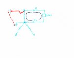
Kindly go through this attachment. The neutral is grounded as shown.my question is
1..when the current returns through neutral wire, why dosent it directly go to the ground as there is a path available at point N.
whts the reason for this.

2..when we say current has to complete its path.what does this mean.
i mean if we have a load on the secondary side of transformer and the transformer is at a good distance from that load.when the circuit is complete, the current flows through hot wire and returns through the neutral wire.is this the meaning of CURRENT HAS TO COMPLETE ITS PATH.? if this is true, then i believe that current will flow back and forth between load and transformer secondary via the hot and neutral wire regardless of the distance.
for example the step down transformer feeding a colony.all the colony loads will be fed from transformer secondary and the current will flow from all the transformer to the load and come back....is it so????
 

Attachments

  • 2.pdf
    91.7 KB · Views: 2
The electric current flows in a closed loop. The ground is out of the closed circuit. Only if will be a leakage from a live phase directly
to ground then the return will be through this ground connection.
 

Attachments

  • Current closed circuit.jpg
    Current closed circuit.jpg
    8.9 KB · Views: 1
The electric current flows in a closed loop. The ground is out of the closed circuit. Only if will be a leakage from a live phase directly
to ground then the return will be through this ground connection.

1-page-001.jpg
so in the above picture, how will the current complete its path.the secondary of both the CT and PT is grounded.where is the return path.

Thanks
 
View attachment 9245
so in the above picture, how will the current complete its path.the secondary of both the CT and PT is grounded.where is the return path.

Thanks

The normal current path is from A through the load to N, while the fault path is.from A to some grounded point, through the earth to the ground electrode connected.to N.
However, if there is a proper EGC connected near the target of the fault then the current will return to N via the EGC rather than through the earth. The earth route will be higher resistance and so will carry relatively little current.
 
View attachment 9245
so in the above picture, how will the current complete its path.the secondary of both the CT and PT is grounded.where is the return path.

Thanks

The return path for the CT generated current (Iabc) is not shown in the diagram. Since only phase currents are shown entering the box ( the relay ), assume a summation point is formed inside.

The PTs & CTs are only grounded for safety reasons. No current is intended to flow through the earth under normal conditions.

The return path for (IABC) is not shown, but a delta connected load can be assumed.

Current leaving a transformer is only interested in returning to the same transformer. Under normal conditions current leaving the transformer travels through the load & then back to the transformer. It is a closed loop no matter the distance.

Let me add that the return circuit for the PTs is not shown either.
 
Last edited:
131019-2351 EDT

jason619:

The schematic you provided is poorly drawn for you to see the complete picture. The person that created the drawing was somewhat sloppy from your perspective because some the details were omitted, but it is an easy and less clutter presentation. It also may not be the actual circuit.

If there is a common connection in the box, called relay, that all of the measurement transformers are referenced to, then this also is probably earthed. Many times a common is called or symbolized as ground, but is not earthed.

Also on the mains side the PTs are connected in a wye fashion, and this could work on a floating delta (ungrounded), but probably would not be a good idea. Thus, the circuit probably implies a mains wye source.

.
 
1..when the current returns through neutral wire, why doesn?t it directly go to the ground as there is a path available at point ?
Because the current has no interest whatsoever in finding its way to ground. :happysad: The notion of ?current takes the path of least resistance to ground? is one of the most frequently cited and well recognized concepts in the electrical industry. And it is a big, fat, lie! :slaphead: Current seeks a path (actually, it seeks any and all available paths) that will return it to the source that set it into motion in the first place. :happyyes:

In your sketch, the current leaves the right side of the transformer winding on the hot wire, goes through the load, then returns to the left side of the transformer winding on the neutral wire. What happens next? Well it does not go to ground! Rather, it travels through the transformer winding once again, and starts heading back towards the load. That is the ?complete path? that you also mentioned in your question.
 
As stated Earth has no function whatsoever, it is just a reference point. Look at the circuit below, it is your circuit down to its simplest form. Only thing the ground reference does is put the neutral conductor and chassis at or near earth potential so if you were to touch the chassis there would be no potential difference to shock you.

Normal load current only flows from the source back to the source in this diagram from L1 to N. Both carry equal current and the sum is ZERO. No current flows through earth as it has no path. If a fault were to occur from L1 to chassis, the green wire is now part of the path and fault current is returned to the source. Since there is no longer any load resistance the fault current is very high so 6 to 50 time higher than the Over Current Protection Device rating. Thus the OCPD operates and disconnect the source thus removing the fault.

Note that even under a fault condition EARTH played no part. No current went through earth. In fact you could remove the EARTH reference and the circuit would operate just fine even under a fault condition.

 
Status
Not open for further replies.
Top