I have searched for any kind of a diagram to explain what I mean, and I have come up empty, so basically the best I can do is give a sequence of operation.
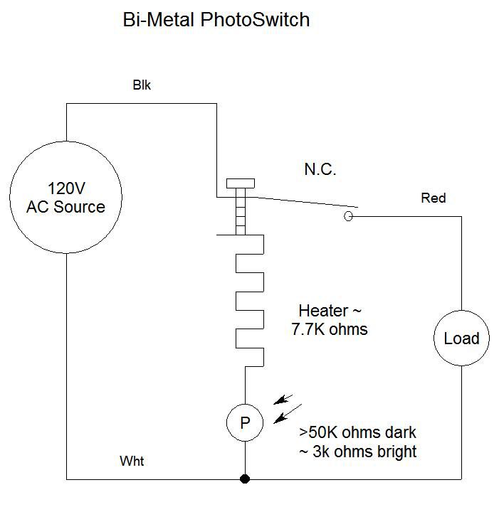
first, using a ladder diagram, you have two lines between the hot and neutral, first line is the N.O contact in series with the load (lamp) the second line is the heater in series with the photo resistor, hot is connected to the contact and heater, the neutral is connected with the load and the photo resistor, now put a small wire wound resistor between the switch leg of the load and the center point between the photo resistor heater, the end result will form a H on its side.
as you will see the resistance of a fully lit photo resistor still does not have a low enough resistance to cause enough heat to be produced by the heater, so the added resistance of the load and the wire wound resistor adds enough with extra head room for different load sizes to open the contacts, the rest of the operation is as you said, (my bad) if the load is removed then the photo resistor again does not have enough to maintain the heat level and the contacts close, again replacing a bad lamp will cause the new lamp to be on for a couple minutes till the heater again heats up with the new load, now apply a very low wattage CFL or LED in place of the incandescent and the lamp wont turn off, this is only for thermo type photo cells not electronic or relay type.
I can't believe I can't find this diagram on the internet, I have dissected a couple photocells and this is how they are wired?
 I screw in a 60 watt lamp let it cycle off, unscrew the lamp wait 2 min's screw it back in, it stayed off, unscrew it again this time wait 10 min's screw it back in it comes on and 2 min's goes back out?