photocell and lighting contactor.

Status
Not open for further replies.
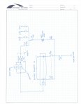
I have a 480/277 V panelboard. This panelboard feeds 277 single phase lighting circuits. It also feed a 277:120/240V transformer. This transformer feeds a 120/240V 12 circuit panelboard.

I have a roadway lighting contactor which I show connected after the 480/277V breakers.
From 120/240V panelboard, I have a 120V feed to a 3 way switch (auto, ON and OFF) which controls the photocell and timeclock (both are connected in parallel) which then control the contactor.

I have 3 lighting contactors for all the lighting circuits in the panelboard. I have to place the photocell on the first light pole. Can a single photocell control 3 contactors. How will my connections be ?
I dont want to feed the switch from 120/240V panelboard. Can I feed it directly from the transformer?
 

mgookin

Senior Member
Location
Fort Myers, FL
You can control as many devices as you want with a photocontrol up to the rated limit of the photocontrol. Contactors often pull around 20 watts each on the control side. Your connections will be parallel.

If you don't feed the switch from the panelboard, how will you have OCPD?

I don't understand why you are putting the photocontrol at the first light; that means you have to have the control wiring coming all the way back to the contactors. Why not have the photocontrol at the first contactor? Are the contactors inside? If so, you could still have a photocontrol receptacle mounted immediately outside that location up high enough to keep kids from tampering with it.
 
Thank you so much for the reply. I have to have photocell on the first light pole as requested by the DOT. So in that case I would have power wire from switch to the photocell and control wire from photocell to the contactors (in the load center)? Am I correct.

I am also attaching a mark up for your reference. If possible could you please mark it up for me.

Thanks, your help is really appreciated.
 

mgookin

Senior Member
Location
Fort Myers, FL
Looking at your photocontrol and switch, on/ auto/ off we do something very similar to that all the time. We are manufacturers of outdoor light controls but instead of a photoresistor we have a GPS radio receiver and run a proprietary algorithm to switch the lights based on lat/ long. The difference being our retail clients use a timeclock to darken the parking lot about an hour after they close and the employees leave - so we're not parallel like you are, but our control feeds the load input of the timeclock to let the timeclock cause an off condition. Your arrangement looks fine if you want the timeclock as a redundant control to make sure it's on, not to ever turn it off with your clock.

I don't understand why you have OCPD twice feeding the timeclock & photocontrol. Wouldn't it be more prudent to tap between the xfrmr and the 30A ocpd to feed the 20A ocpd?

Just curious: What's that heater for?
 
Actually, I forgot to mark it up. the transformer feeds the panelboard with 35A as main breaker and I am feeding the override switch from 20A breaker in the panelboard. The heater is used for the load center. All the equipment shown is inside a load center except the photocell(mounted on first light pole).
 
Status
Not open for further replies.
Top