Power Loss Calculation

Status
Not open for further replies.

gar

Senior Member
Location
Ann Arbor, Michigan
Occupation
EE
131113-1132 EST

Smart $:

See page 276 of "Electric and Magnetic Fields" by Stephen S. Attwood, 3rd Edition, 1949, Wiley, for the equation for the inductance of two parallel wires of infinite length with current in opposite directions per meter of length.

20 mH is in the ballpark for 30 miles, and therefore 6.3 ohms was reasonable for the inductive reactance.

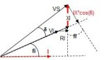
The equation for the impedance of an RL circuit is a standard method from a right triangle for the two vectors.

What may seem more unreasonable is the resistance. There is 5280*30*2 = 316,800 ft of wire or 316.8 1000 ft of wire. This means 0.0032 ohms per 1000 ft. A rather large copper wire.

.
 
Last edited:

Besoeker

Senior Member
Location
UK
I didn't say impossible, just unrealistic. So just what large area and spacing are you implying? How does that relate to using sqrt(X?+R?) for Ze?
The problem states the X and R values which rather infers that the Z is to be calculated from those since no other information is given. The answer offered suggests a short circuit at the receiving end.
Not much else appears to be relevant to the problem as posed. Not even the 30 miles.

But you were questioning the power factor. Certainly for a four-core cable, values suggest a different X/R ratio but for an overhead transmission you have a pretty large loop which could easily account for the 6.3 ohms for X.
We know nothing about the conductor cross-sectional area so can't really speculate on R.
 

beanland

Senior Member
Location
Vancouver, WA
Delivery Voltage

Delivery Voltage

This may be trivial but what about the delivery voltage? If you look at supply voltage and line impedance all you get is maximum possible short circuit current assuming an infinite supply. But whoever is on the receiving end would not like zero voltage delivery. So, what is the allowable voltage drop? 10% 5% Are we adding voltage regulators?

Since the line is inductive, it is the phase angle difference, not the voltage difference, that drives real power.

And, what about overheating the wire? The normal overhead wire current limit is based on allowing the wire not to exceed 75C operating temperature.
 

steve66

Senior Member
Location
Illinois
Occupation
Engineer
I see nothing wrong with the original question or problem.

As others have mentioned, Its a "maximum power transfer problem" pure and simple.

Max. power transfer occurs when the load impedence is equal to the source impedence. You set the load impedence equal to the line impedence, and then calculate how many KW's you get on the end.

I haven't done the calcs, but looking at the other posts, it looks like it gives the correct answer.

The whole point of max. power transfer is to realize that if you make the load impedence smaller than the source impedence, you get less volts on the load, and less power. Make the load impedence higher than the source impedence, and you get less current in the load, and again less power.

Again, power at the load peaks when the load impedence is equal to the source impedence.


This may be trivial but what about the delivery voltage? If you look at supply voltage and line impedance all you get is maximum possible short circuit current assuming an infinite supply. But whoever is on the receiving end would not like zero voltage delivery. So, what is the allowable voltage drop? 10% 5% Are we adding voltage regulators?

Since the line is inductive, it is the phase angle difference, not the voltage difference, that drives real power.

And, what about overheating the wire? The normal overhead wire current limit is based on allowing the wire not to exceed 75C operating temperature.

No need to worry about all that - at least not for this problem. The question simply asks how much power can be delivered. It's probably a homework question - or think of it as a theretical question if you want.
 

GoldDigger

Moderator
Staff member
Location
Placerville, CA, USA
Occupation
Retired PV System Designer
Which brings to mind the early naysayers who pooh poohed the whole concept of central generating stations because matching the load impedance to the generator impedance would melt the generator into copper slag. "Everyone" knew from working with batteries that you had to match impedance to get maximum power. They did not think that what was really needed was maximum energy transfer and efficiency. :)

Tapatalk...
 

gar

Senior Member
Location
Ann Arbor, Michigan
Occupation
EE
131113-1436 EST

steve66:

Whether you consider a Y or delta load the maximum power transfer per phase is not 57.6 MW. I considered one phase of a Y source and got about 28.6 MW.

.
 

steve66

Senior Member
Location
Illinois
Occupation
Engineer
131113-1436 EST

steve66:

Whether you consider a Y or delta load the maximum power transfer per phase is not 57.6 MW. I considered one phase of a Y source and got about 28.6 MW.

.

I haven't actually ran any of the numbers yet, but that does make me realize I made one Major error in my previous post. For Resistive circuits, max. power transfer occurs when the load RESISTANCE is equal to the source RESISTANCE.

This is an AC circuit, and I should have said Max. power transfer occurs when the load IMPEDENCE is the Conjugate of the source impedence. So we should have a load of 0.2 ohms of resistance, and 6.3 ohms of Capacitive reactance at the load.

So the total circuit impedence would only be 0.4 ohms.
 

gar

Senior Member
Location
Ann Arbor, Michigan
Occupation
EE
131113-1729 EST

steve66:

In post 17 I had mentioned that this was an extremely large value. For the Y circuit it is about 19,000^2/(2*0.4) = 451 MW. This clearly did not fit the answer.

If the load is purely resistive, then maximum power transfer occurs when the source series resistance plus the load resistance equals the source inductive reactance.

.
 

Julius Right

Senior Member
Occupation
Electrical Engineer Power Station Physical Design Retired
Julius, thanks for that. My initial calculation was to include the resistance of 0.2 Ohms per phase with the reactance - why is the resistance ignored?
If the OHL length<=80 km [50 miles] the line is considered a "short-line" then
we may neglect R and C [and 1/G=0].In this case, from the attached sketch:
IX*cos(fi)=Vs*sin(d) I*cos(fi)=Vs*sin(d)/X
Actually, the active power passing through the line is: P=VL*I*cos(fi)=VL*Vs*sin(d)/X [MW]
Maximum ?if sin(d)=1- Pmax=VL*VS/X~VS^2/X [MW]
But this is not the PSIL -as I thought before- since Zc=sqrt(L/C) then Zc<>X.
In this case ?I guess- Zc=125 ohm and PSIL= 3 MW [approx.]
 

Attachments

  • OVLine voltage drop.jpg
    OVLine voltage drop.jpg
    6.7 KB · Views: 0

gar

Senior Member
Location
Ann Arbor, Michigan
Occupation
EE
131114-0806 EST

jcbeck:

Can you provide a precise quote of the original question from whatever was the origin?

The given answer seems to imply that the question was --- what is the MVA input to a transmission line 30 miles long with the given values and the load end of the transmission line shorted?

This conclusion comes from a line impedance of sq-root of (6.3^2 + 0.2^2) = 6.303 ohms, a line to neutral voltage 33,000/1.732 = 19053, and an MVA of 19.053^2/6.303 = 57.59 MVA. This is close to 57.62 the quoted answer. And the 57.62 comes from using 6.3 instead of 6.303 .

The answer, 57.62, is not watts (power), nor is it power loss, and it is not how much power (watts) that can be transferred over the line.

Somewhere there is a disconnect between the statement of the problem and the answer. They do not match.

.
 

kingpb

Senior Member
Location
SE USA as far as you can go
Occupation
Engineer, Registered
Short line is less than 50mi; therefore this is a short line. I think everyone agrees on this. Capacitance can be ignored.
You have the receiving end, r, and the sending end, s.

For a short line; Ir = Is, therefore the Vs =Vr +Ir*Z (vectors)
where Z is the total series impedance of line; Z = R +jL (vector)

Since no information for the load was given; assume pf = 1.0 and therefore MW = MVA

Also, for a short T-Line the circuit will be predominantly inductive, which we can see by the fact that the vector Z = 6.3 /_ 88.2 deg

This is found by trig formula of ang = arctan X/R and magnitude is mag = (R2 = X2)1/2

The line is rated 33kV and so assume this is the Vr value line-line, the formula requires line-neutral; so Vr = 19.05kV

Ir = 19.05kV / 6.3 ohm; Ir = 3024 A

MVA = P = Vr x Ir = 57.6MW or MW
 

gar

Senior Member
Location
Ann Arbor, Michigan
Occupation
EE
131114-1010 EST

kingpb:

You performed a calculation for a shorted transmission line. The load is zero resistance, and therefore 0 load power. Under these conditions there are about 19,053/6.303 = 3023 amperes of current, and about 1.8 MW of losses in the transmission line with zero power in the load.

As I mentioned in a previous post the maximum power transfer to a resistive load is when the total series resistance equals the total series reactance. When the maximum power occurs in the total series resistance, then that is also the maximum power condition for any subpart of the resistance. When reactance goes to zero (either no reactive components or at series resonance), then maximum power to the load is when the source resistance equals the load resistance.

.
 

kingpb

Senior Member
Location
SE USA as far as you can go
Occupation
Engineer, Registered
131114-1010 EST

kingpb:

You performed a calculation for a shorted transmission line. The load is zero resistance, and therefore 0 load power. Under these conditions there are about 19,053/6.303 = 3023 amperes of current, and about 1.8 MW of losses in the transmission line with zero power in the load.

As I mentioned in a previous post the maximum power transfer to a resistive load is when the total series resistance equals the total series reactance. When the maximum power occurs in the total series resistance, then that is also the maximum power condition for any subpart of the resistance. When reactance goes to zero (either no reactive components or at series resonance), then maximum power to the load is when the source resistance equals the load resistance.

.

I agree. But according to the OP, this must be what they were after. Either the OP misstated all the details of the question (or context) or it's just a really poorly worded question, it appears the result is what they were looking for.
 
Status
Not open for further replies.
Top