nolabama
Senior Member
- Location
- new orleans la
Safety first always. Thanks for the help man, I hope to have this Monday late evening.
I'm inclined to think not.If the overvoltage fault is because of high DC bus voltage and it is short duration, maybe there is a capacitor switching transient taking the drive out. Any capacitor banks on the high voltage or low voltage side?
I'm inclined to think not.
The DC bus generally has a fairly large capacitor bank. A short duration transient should not greatly affect its terminal voltage.
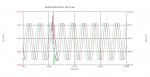
I have had many many cases where I have tied capacitor banks switching on, to drives tripping on DC bus overvoltage. Sometimes on a normal transient, which typically ranges from 15% above the normal waveform peak up to about 30% above the peak of the waveform. Sometimes I have measured a larger than normal switching transient due to a resonance, or magnification. Attached is a waveform of a larger than normal switching transient from a 12 kV, 1200 KVAR utility capacitor bank just down the street from a building where I was monitoring at the 480 V main disconnect. The peak was around 1120 V.
Many 480 V drives will have their dc overvoltage trip if it gets above about 820 V dc for any amount of time, transients included. A 3% or 5% line reactor is often enough to knock down the transient enough, so that it does not trip out the drive.
Nice catch.Attached is a waveform of a larger than normal switching transient from a 12 kV, 1200 KVAR utility capacitor bank just down the street from a building where I was monitoring at the 480 V main disconnect. The peak was around 1120 V.

Nice catch.
The transient doesn't surprise me. But it's all done and dusted with less than a cycle.
The bucket capacitors in a variable frequency inverter are there to provide a low impedance source for the inverter stage and to decouple it from supply frequency.
A sub cycle transient ought not to affect it to any appreciable extent.
Not quite related, but your three phases don't look quite right. The three positive half cycles appear to be at 60deg intervals.
Maybe one is reversed?
Should look like this:

Thank you. I'm just used to looking at this kind of thing.Nice catch yourself!
I agree. A threshold. Not time dependent.Regarding the duration of the transient, I agree with you that there should not really be an effect on damaging the drive. However, the way I understand it, the drive just looks at the voltage instantaneously and if the voltage gets above X, it trips. It does not take into affect the duration.
Thank you. I'm just used to looking at this kind of thing.
I agree. A threshold. Not time dependent.
But on which voltage? Mostly, the inverters I have dealt with use have take control power from a SMPS driven from the DC link. We have some that on a common DC source so ther eis no AC to monitor for over voltage. The bits of the system most likely to be damaged by over voltage are the DC link bucket capacitors and the IGBT inverter devices. Logically, that's where I would expect the voltage monitoring to be.
The DC side has a substantial capacitor bank. A bucket. It provides a low impedance source for the inverter stage. It decouples the output and input frequencies. A sub-cycle transient ought to be swallowed by it and not produce any significant perturbation of the DC link voltage.But if the transient occurs on the AC side near the peak of the waveform, why wouldn't it get passed through to the DC side? So even if monitoring occurred on the DC side, it should still see the transient.