I have two of the same transformers that are wired differently. Each of these transformers are used as a step up transformer and they serve only 1 motor each.
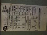
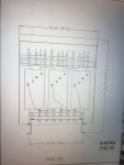
Attached is a picture of the name plate and a detail of the inside.
So we'll start off with the first one- On the secondary HV side, HO HO HO are daisy chained together, then you have H1 H2 H3 leaving the transformer out to the motor.
On the second transformer we have- On the secondary HV side the terminals go HO H1 HO H2 HO H3, just like in the picture. It is wired like follows- left HO to H2, H2 out to motor. Center HO to H3, H3 out to motor. Right HO to H1, H1 out to motor.
To me it looks like the first one is just to make the secondary a Y connection. without connecting the 3 HO's together then it would just be open. Correct me if I am wrong.
Can someone please explain the function of each way these are wired?
Thanks!