• We will be performing upgrades on the forums and server over the weekend. The forums may be unavailable multiple times for up to an hour each. Thank you for your patience and understanding as we work to make the forums even better.

Re-feeding an existing 240/120V Delta service from 480/277V

Merry Christmas

FJE

Member
Location
Carrollton, Ohio
Occupation
Electrical equipment sales
I have a customer (family) that operates a large (for eastern Ohio) farm. They presently have a 400A 240/120V Delta service that feeds the grain handling system, equipment shop, and three residences, along with a retail shop. Of course, the residences and retail shop are fed single phase 240/120V from the A and C phases. The maintenance shop utilizes 120V lighting and receptacles fed from A and C phases. The utility (AEP) supplies the service with two 25kva and one 37.5kva pole mounted oil filled single phase transformers with the neutral connected to the 37.5kva unit.

They are in the process of building a new grain handling system. The added load will be too large to feed from the existing service. In addition, they are installing a solar array on the shop roof. AEP will not connect to a Delta solar system so they are going to install a 400A 480/277V Wye service. The new grain handling system will run on 480V and the solar inverter will have a 480 Wye output to feed back into the grid.

My question is how do we re-feed the existing 240/120V Delta system? We cannot change it to 208/120V Wye because many of the old motors on the existing grain handling system would not work properly on 208V. My idea is to install three single phase dry transformers in a Delta-Delta configuration. The center transformer would be larger and the neutral would be connected to the X2 & X3 terminals on it. The neutral would then be bonded as required for a separately derived system. A, B, and C phases would be connected as usual.

I have seen a similar installation once before in an industrial plant with a 480 corner grounded Delta system. They wanted to feed a 240/120V three phase panelboard for the office. They came off the 480V buss duct and fed three single phase transformers in a Delta configuration. They pulled the neutral off the X2 & X3 of the center transformer and fed the panel. They pulled all the 120V loads from A & C phases. This installation has been in place for over 50 years and is still working fine.

Would my idea for the farm service work, would it meet NEC, and would it be safe? If not, why not? I am not assuming anything here, simply asking for input. Thank you for your time.
 

LarryFine

Master Electrician Electric Contractor Richmond VA
Location
Henrico County, VA
Occupation
Electrical Contractor
Welcome to the forum.

The how is to get a transformer with a 480v delta primary and a 240v delta secondary with a center tap on one phase.

Almost like it was made for it. ;)
 

FJE

Member
Location
Carrollton, Ohio
Occupation
Electrical equipment sales
Every three phase Delta/Delta dry transformer I have ever seen is limited to 5% neutral load on the center tap. That is why I wanted to utilize three single phase transformers with a larger one in the middle to carry the neutral load. Does any manufacturer offer a three phase dry transformer with a full capacity neutral?
 

hillbilly1

Senior Member
Location
North Georgia mountains
Occupation
Owner/electrical contractor
Is this a typical farm service on a pole central to everything? Feed a single phase 120/240 transformer from the 480 volt service, a regular three phase delta for the maintenance shop if it needs three phase. Does the retail shop require three phase, if not, feed it from the single phase transformer. Another way would set a single phase transformer for each house and retail shop. Not knowing the loads, this could be as small as a 30kva each, maybe even smaller. With a 400 amp service already running everything, that would probably be more than enough at each house. You would be wasting money putting in a delta large enough to run everything.
 

infinity

Moderator
Staff member
Location
New Jersey
Occupation
Journeyman Electrician
Every three phase Delta/Delta dry transformer I have ever seen is limited to 5% neutral load on the center tap
Are you sure about the 5%? That number doesn't seem correct for 3 phase, 4 wire, Delta secondary. I do recalling hearing about 5% on the high leg but not on the 120 volt loads.
 

Elect117

Senior Member
Location
California
Occupation
Engineer E.E. P.E.
1) Consult a licensed professional.
2) You can use 3 - 480-120/240V transformers and wire them 3ph delta on the secondary and 3ph delta on the primary. It will work the same as a dry type 3ph 480V delta primary and 3ph 120/240V delta secondary.
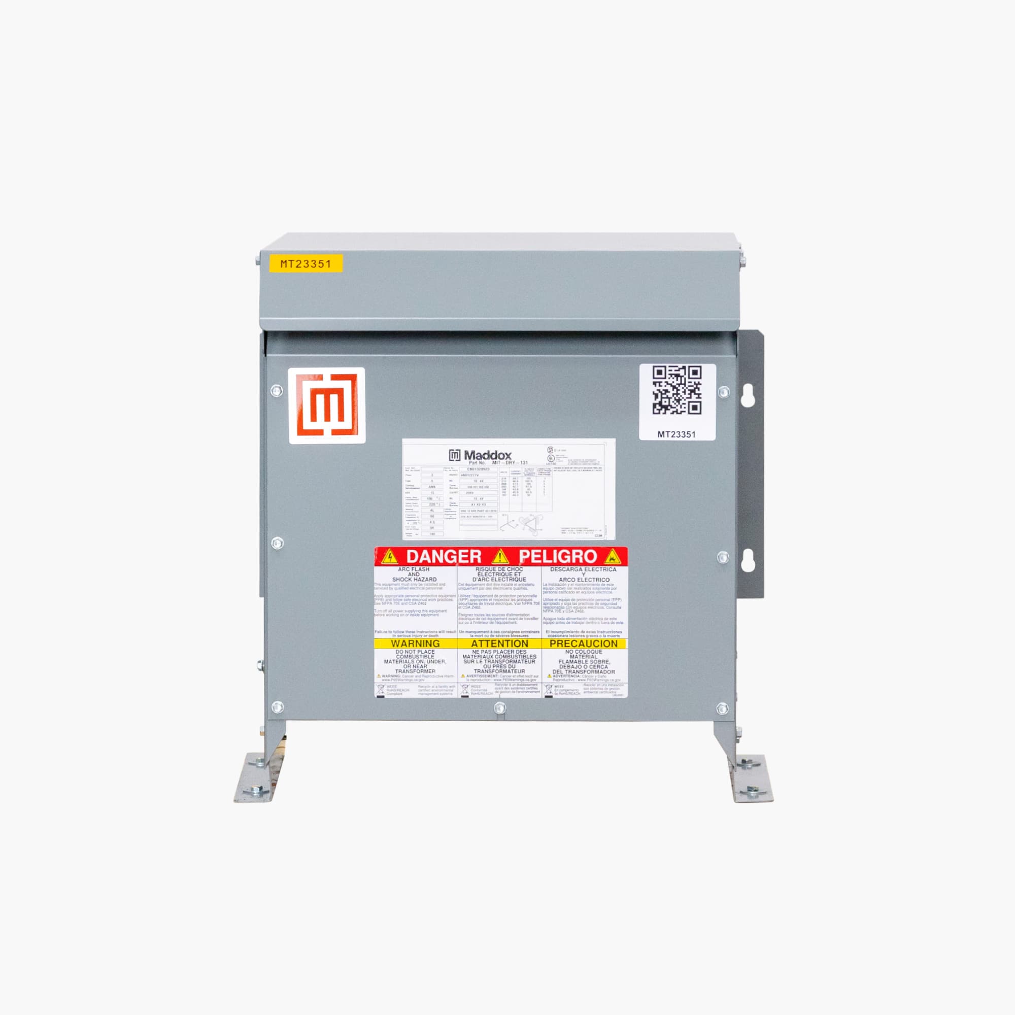
3) From reading Maddox's website it talks about the 5% leading to the derating of the transformer (most likely since unbalance current will circulate). It isn't a big deal if done correctly by an electrician or engineer. They should be able to pull that math together and size it appropriately.
4) Yes the install can be done in compliance with the NEC. There is nothing wrong with having multiple voltages for different uses.

Honestly, everything you mentioned can be done safely.
 

wwhitney

Senior Member
Location
Berkeley, CA
Occupation
Retired
Every three phase Delta/Delta dry transformer I have ever seen is limited to 5% neutral load on the center tap.
Here's the product page of a random 480V delta: 240V/120V delta transformer:


It says "The center tap can provide 5% of the total kVA rating without taking away from the overall capacity."

Say I had a 30 kVA such transformer, with B the high leg, and suppose my loading is 15 kVA 3-phase 240V, 5 kVA A-B, 5 kVA B-C, 2.5 kVA A-N and 2.5 kVA N-C. That's a balanced loading, each 240V coil has 10 kVA on it, and the two 120V coils have the same load. As the load adds up to 30 kVA, that's within the transformer's rating.

The quoted sentence is not instructing us to take 5% * 30 kVA = 1.5 kVA and to limit the A-N and N-C loads to 1.5 kVA. In the above loading, in order to get 2.5 kVA through the neutral, one of the 120V legs would have to be carrying 0 kVA, and so the total load when the neutral is carrying 2.5 kVA is only 27.5 kVA. Not a problem, no coil ever sees more than the expected current of 30 kVA / 3 / 240V = 41.7A.

Rather, I think the sentence quoted is giving a limited additional allowance to exceed 41.7A through one coil if the imbalance is low enough. E.g. suppose the 5 kVA of 120V loads were divided 2 kVA A-N and 3 kVA N-C. Now at the full loading of 30 kVA, we do have 1 kVA of unbalanced neutral loading simultaneous with the full loading. But 1 kVA < 5% * 30 kVA, so that's OK. The N-C coil would actually be carrying 45.8A, but that's OK. Since the total kVA does not exceed the 30 kVA rating, the A-N coil is carrying less current that its rating, and the total transformer heating is within limits.

Would appreciate confirmation from those more experienced, as the above is just my inference. I don't see what else it could plausibly mean.

Cheers, Wayne
 

Elect117

Senior Member
Location
California
Occupation
Engineer E.E. P.E.
As you already know, it is allowed because of the exception for a different voltage. I have used that for an exception once. Had to point it out to the inspector though.

I wonder if calling for two services would impact the benefit of the solar install at 480V? If it is all on one service then wouldn't more of their usage be offset? Rather than having one meter offset and the other nothing? Maybe that is also POCO / rate schedule dependent.

Maybe it would be more beneficial if they are allowed to over sell for a decent amount.


And, Wayne, that was basically how I understood it. If you full load the 2 legs that are not split, and then have unbalance in the split legs, the neutral unbalance current will circulate making the other two legs more than full load. I think their 5% number is like a overrating factor on the full load. Granted when I look at other websites like Larson's electronics, they don't include that note.
 

wwhitney

Senior Member
Location
Berkeley, CA
Occupation
Retired
If you full load the 2 legs that are not split, and then have unbalance in the split legs, the neutral unbalance current will circulate making the other two legs more than full load.
Can you elaborate on what you mean by the last part of that sentence?

For example, take the last case in my post #9. I get secondary currents of 41.7A in coils A-B and C-B, 45.8A in N-C, and 37.5A in A-N. Then for a 480V primary, I get primary coil currents all equal to 20.8A. I'm not seeing what current circulates or how the A-B and C-B secondary currents would be increased by the A-N-C imbalance.

Thanks,
Wayne
 

Elect117

Senior Member
Location
California
Occupation
Engineer E.E. P.E.


I don't know if I am going to be that good at explaining it.

All the currents through the transformer phases enter and exit through the nodes. The split phase, where unbalanced single phase loads exist will have an increase in the phase current through the total 240V winding.

With 45.8-37.5 = 7.5A to circulate (or maybe a fraction of that?, I am unsure) because a Delta transformer the currents leaving the node should add to zero.
 

wwhitney

Senior Member
Location
Berkeley, CA
Occupation
Retired
With 45.8-37.5 = 7.5A to circulate (or maybe a fraction of that?, I am unsure) because a Delta transformer the currents leaving the node should add to zero.
It's this use of the word "circulate" I'm not getting. It seems to imply that the imbalance between A-N and N-C would cause increased currents A-B or B-C. I'm not seeing that. I'm getting that in the balanced case the secondary currents for (A-B, B-C, C-N, N-A) are (41.7, 41.7, 41.7, 41.7), while in the unbalanced case the secondary currents are (41.7, 41.7, 45.8, 37.5). I.e. the unbalance move some secondary current from N-A to C-N, and that's it. And I'm getting that the primary currents are identical in the two cases.

That obviously slightly increases the heating in the secondary of the transformer, as 45.82 + 37.52 > 41.72 + 41.72. But it would be a small effect, which is what I assume the 5% allowance is about.

So do I have the current wrong in the unbalanced case?

Cheers, Wayne
 

tortuga

Code Historian
Location
Oregon
Occupation
Electrical Design
I have a customer (family) that operates a large (for eastern Ohio) farm. They presently have a 400A 240/120V Delta service that feeds the grain handling system, equipment shop, and three residences, along with a retail shop. Of course, the residences and retail shop are fed single phase 240/120V from the A and C phases. The maintenance shop utilizes 120V lighting and receptacles fed from A and C phases. The utility (AEP) supplies the service with two 25kva and one 37.5kva pole mounted oil filled single phase transformers with the neutral connected to the 37.5kva unit.

They are in the process of building a new grain handling system. The added load will be too large to feed from the existing service. In addition, they are installing a solar array on the shop roof. AEP will not connect to a Delta solar system so they are going to install a 400A 480/277V Wye service. The new grain handling system will run on 480V and the solar inverter will have a 480 Wye output to feed back into the grid.

My question is how do we re-feed the existing 240/120V Delta system?
400A @ 480V service is probably three 100kva transformers? 300kva? What I have done recently is ask the utility for 3 100kVA in a 240V full delta configuration that way your not paying for the extra transformer (24/7 losses) and the farm does not need a 70E program for the 480V. You just add a second 400A disconnect and tell the grain equipment mfr its 240V.
Not sure about the solar though, but my guess is they would allow a backfeed of a full delta, whats there now is an open delta.
 

jim dungar

Moderator
Staff member
Location
Wisconsin
Occupation
PE (Retired) - Power Systems
It does depend on how the center tapped delta transformer is constructed and the power factor of the loads and the amount of 3-phase loading. For the most part, the cheapest construction will have this 5% loading issue.

Many decades ago Square D's Sorgel transformer division published an application note on 240/120 Four Wire Delta Connection. The last time I saw it in print was in 1992 using bulletin #7400PD9201, I have never been able to find it since then. It appears this bulletin number was reissued with a different topic.

But in summary, in a 100% imbalance, one half of the center tapped winding will experience roughly 5/6 of the single phase loading. This is why most of these utility configurations are made using two units in an open delta.
 
Last edited:

wwhitney

Senior Member
Location
Berkeley, CA
Occupation
Retired
It does depend on how the center tapped delta transformer is constructed . . .
But in summary, in a 100% imbalance, one half of the center tapped winding will experience roughly 5/6 of the single phase loading.
Thanks. Your post, particularly the 5/6, reminded me of what I was missing. Namely that with a delta secondary, because the coils form a loop, the coil currents are not determinate just from the loading. You need some further information, typically the coil impedances.

For example, say you have a (closed) delta secondary with the only load supplied A-B and a load current of 1A. Then the coil currents could be A-B = 1A ; B-C = C-A = 0A. That is what you would get if one of the B-C or C-A coils were damaged and open circuit.

Or the coil currents could be A-B = 0; B-C = C-A = 1A. That's what you would get if the A-B coil were damaged and open circuit.

Or the coil currents could be A-B = 2/3A; B-C = C-A = 1/3A. That what you would get if all the coils are the same impedance, so that the two sources (A-B, or A-C-B) divide the current in inverse proportion to the impedances.

And then if the A-C coil is center-tapped, and the only load current is instead 1A A-N, and all the coils have the same impedance per unit length, the coil currents would be A-N = 5/6A ; A-B = B-C = C-N = 1/6A.

Cheers, Wayne
 

jim dungar

Moderator
Staff member
Location
Wisconsin
Occupation
PE (Retired) - Power Systems
Thanks. Your post, particularly the 5/6, reminded me of what I was missing. Namely that with a delta secondary, because the coils form a loop, the coil currents are not determinate just from the loading. You need some further information, typically the coil impedances.

For example, say you have a (closed) delta secondary with the only load supplied A-B and a load current of 1A. Then the coil currents could be A-B = 1A ; B-C = C-A = 0A. That is what you would get if one of the B-C or C-A coils were damaged and open circuit.

Or the coil currents could be A-B = 0; B-C = C-A = 1A. That's what you would get if the A-B coil were damaged and open circuit.

Or the coil currents could be A-B = 2/3A; B-C = C-A = 1/3A. That what you would get if all the coils are the same impedance, so that the two sources (A-B, or A-C-B) divide the current in inverse proportion to the impedances.

And then if the A-C coil is center-tapped, and the only load current is instead 1A A-N, and all the coils have the same impedance per unit length, the coil currents would be A-N = 5/6A ; A-B = B-C = C-N = 1/6A.

Cheers, Wayne
We also have to deal with the circulating current, especially if the 3 transformers are not the same size.
 

wwhitney

Senior Member
Location
Berkeley, CA
Occupation
Retired
We also have to deal with the circulating current, especially if the 3 transformers are not the same size.
So the circulating current is the indeterminancy I mentioned. It is unknown from just the loading.

In my previous example of a 1A load applied A-B to a 3 wire delta secondary I wasn't using a good sign convention. If we denote the 3 coil currents via a triple (A-B, B-C, C-A), then using a better sign convention the 3 possibilities I mentioned are:

(1) (1,0,0) (the obvious one, and what you'd get with a single phase transformer or if B-C-A was open circuit)
(2) (0,-1,-1) (what you'd get if the A-B coil is open circuit)
(3) (2/3, -1/3, -1/3) (what you'd get if all the coils are equal impedance)

The difference between (1) and (2) is a circulating current of (1,1,1); and the difference between (1) and (3) is a circulating current of (1/3, 1/3, 1/3).

Of course, this example just covers the "single phase" case where there is only phase of load current, so each current can be expressed as a single real number. For loading on multiple coils, we need to keep track of the currents as phasors.

Cheers, Wayne
 

wwhitney

Senior Member
Location
Berkeley, CA
Occupation
Retired
I'm getting that in the balanced case the secondary currents for (A-B, B-C, C-N, N-A) are (41.7, 41.7, 41.7, 41.7), while in the unbalanced case the secondary currents are (41.7, 41.7, 45.8, 37.5).
So under the equal impedance per unit length hypothesis, that would still be correct for this particular unbalanced case, assuming the A-N and C-N load currents are in phase with each other. The load currents are equal to the balanced load currents plus a load of 4.2A C-N plus a load of -4.2A N-A. Each of those unbalanced load contributions would induce a circulating current, but as the unbalanced loads are on the same coil and are equal but of opposite signs, the two circulating current contributions cancel in coils A-B and B-C, so the naive answer I gave earlier is still correct.

Cheers, Wayne
 
Top