justin13me
Member
- Location
- CANADA
So you are trying to save cable by wanting to go from new switch to light, instead of new switch to old switch?
Condratulations now you got it. :lol:
170327-0915 EDT
K8MHZ:
justin13me has implemented my suggestion 1 in post #36 to divorce the "exclusive or" from the input switches and locate the "xor" somewhere else.
The truth table for XOR is:
A B . Out .... A and B are binary inputs and Out is the resulting binary output
0 0 = 0
0 1 = 1
1 0 = 1
1 1 = 0
It should be noted that this a basic part of binary addition. Binary addition is:
C A B . Out where C is carry from the previous stage
0 0 1 = 1
0 1 0 = 1
0 1 1 = 0 with carry
1 0 0 = 1
1 0 1 = 0 with carry
1 1 0 = 0 with carry
1 1 1 = 1 with carry
For comparison AND is:
A B . Out
0 0 = 0
0 1 = 0
1 0 = 0
1 1 = 1
Have not proofread, have to leave.
.
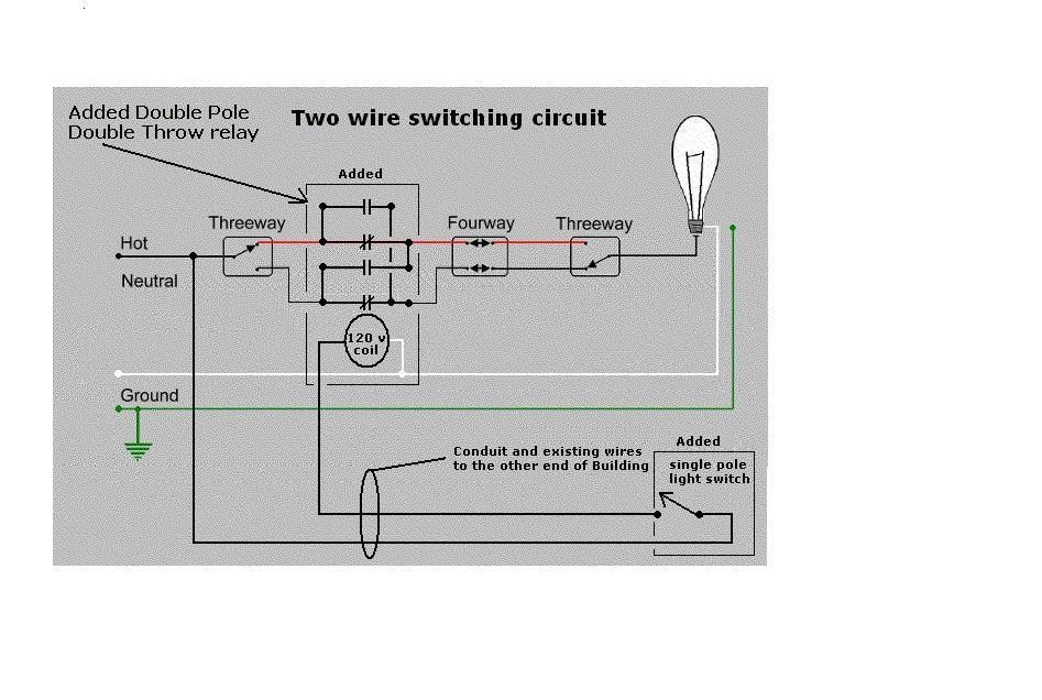
Solution was simple with the added relay. The explanation in binary format takes a bit longer.And here we go using a sledge hammer to put in a thumbtack.
Let's make the simple complicated. :roll:
Solution was simple with the added relay. The explanation in binary format takes a bit longer.

Very cool... there's just one small remaining problem:
If those switches were mounted vertically, they'd violate 404.7.
I am glad that the OP specifically said that the plan is to simply run new wire but continue the discussion for theory fun; because I am happy to dive in
My first thought along the lines of over-complicating things so that 2 wires could be used in a 3-way setup is 'diodes'. Use a 4 way switch with a diode connected across two terminals. Depending on switch position the circuit will conduct electricity in one direction or the other.
With 2 diode/switch assemblies you conduct current only when both diodes are 'pointed the same way'. This gets you 3-way switching with only two conductors between the switches. Problem is that you now have reduced voltage at your load, so you still need something to provide full voltage to the load.
I think that ronaldrc has the most elegant solution other than just running the new conductors. As I understand it, he used a single pole switch to turn a relay on and off, and wired the terminals of the relay to look like a 4-way switch. So you would add in a new 3-way/4-way switching circuit to control the light, with _one_ of these 'switches' actually being a relay, and you would use the existing 2 conductors to control the relay.
-Jon


