Relay settings

Status
Not open for further replies.

charlie b

Moderator
Staff member
Location
Lockport, IL
Occupation
Retired Electrical Engineer
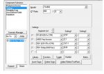
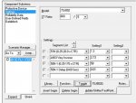
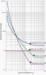
I need a translator, or at least an instructor. I have gone through the exercise of comparing a set of fuse curves and an MV cable's damage curve. I now need to check the cable against an upstream relay. I have been given the settings, but I do not know how to interpret them. Can anyone tell me how to use the information shown on the attached settings sheets?
 

Attachments

  • Relay Settings - 01.jpg
    Relay Settings - 01.jpg
    121 KB · Views: 0
  • Relay Settings - 02.jpg
    Relay Settings - 02.jpg
    121.7 KB · Views: 0

Pharon

Senior Member
Location
MA
I'm just gonna take a shot in the dark here, in the interest of maybe learning something myself:

"51 (0.5-20 x CTR), setting: 3.57" -- 51 is the AC inverse time relay (short/long time), CTR = CT Ratio, 600/5 or 120; so 3.57 x 120 = 428.4A

Very Inverse (see attached pic)

"50-1 (0.5-175 x CTR), setting: 121.1" -- 50 is the instantaneous time function, 121.1 x 120 = 14,532A @ 0.01 seconds

The 51N relay sounds like residual ground fault current settings, using the same logic above for the trip points.
 

Attachments

  • inverse-types.jpg
    inverse-types.jpg
    10.4 KB · Views: 0

kingpb

Senior Member
Location
SE USA as far as you can go
Occupation
Engineer, Registered
The relay in question is a Siemens, Model 7SJ802. The previous post is accurate.

However, the thumbnail provided appears to be missing a Time Dial setting for this relay.

This needs to be confirmed to determine the actual adjustment for the 51 and 51N, both.

Also, the 51N means that the relay is using the three single phase CT current inputs to calculate the residual current. The alternative is if it said 51G, then that would mean you are using a zero sequence CT; all three phases pass through the CT to measure current.
 

JoeStillman

Senior Member
Location
West Chester, PA
51 is the long-time pickup
ANSI Very Inverse refers to the slope of the long time segment (or else the short time, see below).
50-1 is the instantaneous pickup
50-1 is (I think) the short-time delay.

If you hit the "Toggle" button, you switch between the phase curve and the ground-fault curve.

If you assign the relay to a TCC file in SKM, you can adjust each setting and watch how the shape of the curve changes. I like to make a temporary TCC file for the one device, just so I can be sure I understand the settings.
 
Status
Not open for further replies.
Top