Screw in CFL's and actual load

Status
Not open for further replies.

gar

Senior Member
Location
Ann Arbor, Michigan
Occupation
EE
101127-0728 EST

ELA:

I can make such a measurement, but at this time I do not want to go thru the major setup to do it.

The current marked on the bulb, 0.18 A for the 13 W bulb, is the RMS current and for 25 lamps is of no significance for a 20 A breaker. I believe that is why wireguru asked his question. But peak inrush might be. But without a more accurate estimate than my wild guess of what this peak energy might be it is still an open question on the reason.

I also think it would be unlikely that there would be 25 11 or 13 W bulbs on one switch. But iwire has a good reason.


wireguru:

its interesting the utilities would be pushing a product with such poor power factor so hard (especially to residential users that dont get billed for kvar).

why dont they make the CFLs with a better ballast circuit with PFC and have the tube replaceable?
Cost and political pressure. Incandescents are being banned.

If you compare the load and heating of wires, and energy consumption, between incandescent and fluorescent lighting for the same amount of light effectiveness, then fluorescent wins. Psychologically it may be a different story.

.
 

kwired

Electron manager
Location
NE Nebraska
The total amount of power factor problems to the utility possibly takes hundreds of homes to equal the amount created by one relatively small industrial plant. CFL's has probably made that ratio a little smaller but it is still a large ratio I would guess.

How many 13 watt CFL's would it take to equal the amount of power factor created by average 10 hp motor?

How many 10hp or larger motors are found in an industrial plant?

How many motors over 1 hp are found in an average dwelling?

If there is any over 1 hp how many of them are continous loads of at least 8 - 12 hours a day.
 

gar

Senior Member
Location
Ann Arbor, Michigan
Occupation
EE
101127-1150 EST

kwired:

The CFL poor power factor is a result of a much different current waveform than that of an induction motor. The motor current is close to a sine wave but shifted in phase angle relative to the applied voltage. A capacitor input filter load, a CFL is in this category, has a moderately narrow current pulse roughly centered at the voltage peak.

Incandescent lamp load in the US has been a substantial part of the load on power plants.

A broad range of useful information on CFLs is in the following discussion:
http://en.wikipedia.org/wiki/Compact_fluorescent_lamp

.
 

ELA

Senior Member
Occupation
Electrical Test Engineer
101127-0728 EST

ELA:

The current marked on the bulb, 0.18 A for the 13 W bulb, is the RMS current and for 25 lamps is of no significance for a 20 A breaker.

.

I think the issue here is "crest factor". While the RMS current is low the peak currents are high.

These high peak currents can cause waveform distortion issues.

It is also likely there are other loads on the circuit and so a ~25 amps peak current due to lamps only could be an issue.
 

gar

Senior Member
Location
Ann Arbor, Michigan
Occupation
EE
101127-2134 EST

ELA:

A QO20 is primarily a thermal device, with magnetic assistance at high currents. Without looking up any specifications I suspect it is mostly thermal to 80 to 100 A. I can load one to the 80 A range for maybe 5 seconds without tripping. However, with multiple repeats with maybe 20 second spacings it will trip after one or two starts. This is my DeWalt radial arm saw at the end of 100+ ft of #12 copper and sourced with 120 V.

A continuous 5 A RMS load on a QO20 will only dissipate about 1/16 the power in the breaker as at 20 A. Thus, the breaker element is quite cool. 40 to 50 A of peak current but with an RMS of 5 A thru this breaker should be no different than a 5 A sine wave.

This is the reason I believe the manufacturer's caution may be related to inrush current.

A pure magnetic breaker with no dashpot would be different.

.
 

kwired

Electron manager
Location
NE Nebraska
101127-1150 EST

kwired:

The CFL poor power factor is a result of a much different current waveform than that of an induction motor. The motor current is close to a sine wave but shifted in phase angle relative to the applied voltage. A capacitor input filter load, a CFL is in this category, has a moderately narrow current pulse roughly centered at the voltage peak.

Incandescent lamp load in the US has been a substantial part of the load on power plants.

A broad range of useful information on CFLs is in the following discussion:
http://en.wikipedia.org/wiki/Compact_fluorescent_lamp

.

Does this poor power factor in the CFL's installed in dwellings have much effect on the utility as compared to what industrial motors with no correction would have?

Sure they are going to add up but I'm guessing the industrial loads are significantly higher than all of the residential load - especially if excluding 100 percent power factor loads.

Commercial and industrial lighting is likely the next largest load on the utility in most areas, but most of that is high power factor these days. With increases in electronic ballasts there may be more harmonic issues than there once was.
 

gar

Senior Member
Location
Ann Arbor, Michigan
Occupation
EE
101128-0855 EST

kwired:

One definition of power factor of a load is the ratio of "POWER CONSUMED IN THE LOAD" to "RMS VOLTS ACROSS THE LOAD" times "RMS CURRENT THRU THE LOAD".

The power consumed in the load would be based on all the energy fed into the load that is not returned to the source. A simple way to view this consumed power is that it is all the power in the load dissipated as heat, mechanical work, and radiated energy.

If we assume a sine wave source for the voltage independent of the load current, then for an induction motor load the current will be close to a sine wave but shifted in phase angle. This produces an apparent power from the VA calculation that is greater than work power and the power factor is less than 1 in a lagging direction. The current in the generator (alternator) and the distribution system is greater than that which is necessary to do real work. Thus, more losses in the generator and the connecting wires than is really necessary. With this type of load the source and distribution losses can be reduced by power factor correction with shunt capacitors at the load. This does not reduce losses within the load.

Devices with a capacitor input filter have a peaked current waveform at about the peak of the AC voltage. Low power factor resulting from this type of load is not correctable by a simple shunt capacitor. More complex filtering is required.

Power factor as a means of describing a problem is a useful tool. However, the real goal is to obtain maximum useful load power with a minimum RMS supply current. Supply current is what determines source and distribution losses.

.
 

kwired

Electron manager
Location
NE Nebraska
101128-0855 EST

kwired:

One definition of power factor of a load is the ratio of "POWER CONSUMED IN THE LOAD" to "RMS VOLTS ACROSS THE LOAD" times "RMS CURRENT THRU THE LOAD".

The power consumed in the load would be based on all the energy fed into the load that is not returned to the source. A simple way to view this consumed power is that it is all the power in the load dissipated as heat, mechanical work, and radiated energy.

If we assume a sine wave source for the voltage independent of the load current, then for an induction motor load the current will be close to a sine wave but shifted in phase angle. This produces an apparent power from the VA calculation that is greater than work power and the power factor is less than 1 in a lagging direction. The current in the generator (alternator) and the distribution system is greater than that which is necessary to do real work. Thus, more losses in the generator and the connecting wires than is really necessary. With this type of load the source and distribution losses can be reduced by power factor correction with shunt capacitors at the load. This does not reduce losses within the load.

Devices with a capacitor input filter have a peaked current waveform at about the peak of the AC voltage. Low power factor resulting from this type of load is not correctable by a simple shunt capacitor. More complex filtering is required.

Power factor as a means of describing a problem is a useful tool. However, the real goal is to obtain maximum useful load power with a minimum RMS supply current. Supply current is what determines source and distribution losses.

.

I have read through your posts again and think I am getting most of what you are saying.

I understand that the measured current level appears to be higher as compared to what the wattage is supposed to be. One may initially assume poor power factor similar to what happens in an inductive load, but the peaks of current and voltage are mostly in phase with each other but the voltage and current ratio is not linear throughout the cycle.

Correct me if I am on the wrong track.

Wouldn't the use of a true RMS ammeter give you reading closer to what should be expected for a given wattage lamp? And if so there is really little or no power factor issue but more of a harmonic distortion. There isn't really much if any current here that is not doing any work like there is in a motor, right?

The true RMS meter would read what the real load effect is on the source.
 

kwired

Electron manager
Location
NE Nebraska
POCO watt-hour meters will record the true energy used by these lamps won't they?

All we need is some company to start selling snake oil remedies for a problem that does not exist.
 

ELA

Senior Member
Occupation
Electrical Test Engineer
101127-2134 EST

ELA:

A QO20 is primarily a thermal device, with magnetic assistance at high currents. Without looking up any specifications I suspect it is mostly thermal to 80 to 100 A.

40 to 50 A of peak current but with an RMS of 5 A thru this breaker should be no different than a 5 A sine wave.

.

Here, I looked this up for you..

http://static.schneider-electric.us/docs/Circuit%20Protection/Miniature%20Circuit%20Breakers/QO-QOB%20Circuit%20Breakers/730-3.pdf

Not sure about these statements and what your real point is? I agree that at some point "peak currents" will trip the magnetic trip. Near 10x or 200amps very short period inrush will trip this breaker. So - if the 25 lamps total inrush adds up to that amount, for the appropriate time according to the curve, the breaker will trip.

Don't understand why you talked at all about thermal.

This is the reason I believe the manufacturer's caution may be related to inrush current.

A pure magnetic breaker with no dashpot would be different.

.

Gar,
Too much speculation. As you often tell people... "I recommend you get some parts and do some testing." :)

As stated I agree if the inrush is very great that the breaker will trip. I have dealt with a lot of capacitive inrush issues and have replaced QO120 breakers with QO120HM for such issues. These were typically very large capacitors in Servo drives with > 260 amp inrush currents for 1-2 cycles.


I still think there is a concern for waveform distortion issue due to peak currents each half cycle.
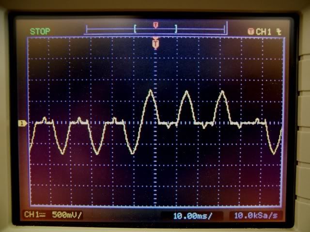
Most of us can "see" the distortion caused by a a laser jet printer when it prints, as a slight oscillation in the lamp brilliance. A while back I measured this laser jet current waveform:
Laserjetcurrentwhileprinting.jpg


Scale is 5A/div.

So my point is that 20-25 amps peaks every half cycle would be clipping the peak of the waveform.
 

gar

Senior Member
Location
Ann Arbor, Michigan
Occupation
EE
101128-1357 EST

ELA:

The reason I bring up thermal is because the QO breaker is basically a thermal device. It has a bimetal element for sensing current. Also the routing path of current inter-related with the trip mechanism, a loop, on large currents also provides a force to trip the latch. A very nice breaker design.

Until the currents are large enough the magnetic effect has little influence on tripping. From the Sq-D trip time curve you can see that the magnetic effect occurs in the range of 6 to 10 times breaker rating. Once you reach the 1 cycle (16 MS) time then the clearing time is a function of opening time constant of the breaker mechanism and arc quenching.

In 1962 I made some measurements on an MP1500 1/2 A, a Sq-D 15 A, and a Heinemann AM12HK relative to opening time. MP stands for Mechanical Products and that breaker was an aircraft hot wire breaker.

The MP1500 had a contact opening distance of 0.06". Time was 0.8 MS and average velocity of opening was 78 inches/second.

The QO-15 figures were 0.5", 4 MS, and 125 inches/second.

The AM12HK figures were 0.16". 2.4 MS, and 65 inches/second.

Since the Sq-D can completely open in 4 MS it appears that arc quenching is part of the 1 cycle clearing time period.

Since the Sq-D is primarily a thermal device for peak currents less than 6 times its rating there is no interest in the crest value until about 6 times rating is exceeded. For extremely high pulse currents of very short duration it will be the energy produced in the breaker that will determine whether tripping occurs. For currents over about 10 times rating and of moderate duration the QO will trip on the magnetic effects.

I totally agree that the voltage peaks will be flattened by the large current from capacitor input filters.

.
 

gar

Senior Member
Location
Ann Arbor, Michigan
Occupation
EE
101128-1431 EST

kwire:

I have never evaluated a power company watt-hour meter for the effects of a very distorted current waveform. Nor for any other waveform. Theoretically the watt-hour meter will measure actual power (energy) used. However, the high frequency components of a very peaked waveform may be filtered out and thus produce reading errors. Probably in the customers favor.

You are getting an understanding of what I have been saying. Definition of power factor is the important consideration here. From M. B. Stout's book on "Analysis of A-C Circuits", p18, "Power in an Alternating-current Circuit":
The product of E by I is called the "apparent power", probably because the early workers felt that the product EI should represent power, in line with their experience with direct current. Apparent power is a useful concept in many places in electrical engineering. The unit for his quantity is called the volt-ampere, to avoid confusion with the "true power", measured in watts. Alternating-current generators, transformers, and other equipment are rated in volt-amperes (or kva), rather than watts, because the voltage is set by the design, and the permissible current by the heating effect of the windings. Accordingly, the designer can guarantee his machine to carry safely a specified value of volt-amperes, but not any fixed number of watts, for he cannot foresee or control the type of load that the customer may choose to connect to the machine.

The ratio of the power to the apparent power is called the power factor of the circuit. For the pure sine wave circuit the power factor equals cos theta. ----

Later on p 28:"Power Factor in Circuits with Complex Waves."
Power factor for a circuit in which the current and voltage have irregular wave forms may be defined in the same way as for sinusoidal waves. That is, Power Factor = W/ Eeff*Ieff, ----

There may be others that choose to define power factor in some different way.

From your earlier post:

I understand that the measured current level appears to be higher as compared to what the wattage is supposed to be. One may initially assume poor power factor similar to what happens in an inductive load, but the peaks of current and voltage are mostly in phase with each other but the voltage and current ratio is not linear throughout the cycle.
For this type of discussion always think in terms of RMS measurements, eff as Stout described the values. So your statement is correct. The actual power consumed by the device, CFL, divided by the RMS voltage, calculates a current less than the measured RMS current.

Wouldn't the use of a true RMS ammeter give you reading closer to what should be expected for a given wattage lamp? And if so there is really little or no power factor issue but more of a harmonic distortion. There isn't really much if any current here that is not doing any work like there is in a motor, right?

The true RMS meter would read what the real load effect is on the source.
No. You need to use a meter that measures power to the load to determine the actual power to the load.

If you were to plot the instantaneous current and voltage to a load, multiply these two curves together at each instant of time, average the result over an adequate time period, then you would get the average power for that time period.

.
 

Ragin Cajun

Senior Member
Location
Upstate S.C.
Been out of town. Yes, I used a Illl-a-Watt.
While at my daughters, I noticed she has a 26W GE CFL that indicated 0.39A, or ~47VA, again dismal pf.

Whatever, these CFL's are a crock. The lifetime is no where claimed based on failures at my home and others. The "green" movement as one acquaintance said, is a fraud!


RC
 

gar

Senior Member
Location
Ann Arbor, Michigan
Occupation
EE
101128-2022 EST

Ragin:

Your measurement on the GE 26 W seems normal. The 26 W CFL is probably equivalent to about a 75 W incandescent. A 75 W incandescent would draw about 0.63 A. From a transmission line and generator power loss point of view for a comparable CFL there would be about 62% less energy wasted in the distribution system, (0.39/0.63)^2 = 0.38 . The energy that needed to be generated for the CFL is 26/75 = 35% of that for the incandescent. These are big savings.

CFL life, I have a number that are left on continuously and the life has generally been good. Only a few have had a high infant mortality. Sure beats have to replace incandescents fairly often in continuous on locations.

Most of my lighting is 8' Slimlines and their power factor is much better than CFLs and the current waveform is close to a sine wave.

.
 

gar

Senior Member
Location
Ann Arbor, Michigan
Occupation
EE
101128-2040 EST

kwired:

I will restate my comments on power factor.

My starting position is Prof. Stout's definition for power factor.

Power factor of a load is the REAL POWER CONSUMED BY THE LOAD / (Vrms * Irms) independent of the wave shapes of the voltage and current.

Unless specifing instantaneous power one will usually assume a statistically stationary process (meaning steady state) and that the power is averaged over a very large time or over a range of 2*Pi*N cycles. Where N is an integer, and 2*Pi is one full cycle.

All results for different waveforms derive from this definition. So in the special case of a sine wave voltage and a sine wave current where the current is of the same frequency and phase locked to the voltage, then PF = cos theta. Where theta is the phase difference between the voltage and current.

The least transmission losses occur when the load power factor is 1.00 .

This does not mean that a CFL with a poor power factor is a bigger burden on a system than an incandescent that produces the same light level.

There may be others that want to use a different definition of power factor than what I use. Then in some cases they would draw different conclusions. I think you will find that most people use the basic definition I am using.

If you can work from a common definition for something, then communication is much easier.

Is our discussion helping you develop an intuitive feeling for power factor?

.
 

wptski

Senior Member
Location
Warren, MI
Returned from T'Day dinner only to find the light on a timmer OFF. A hardly used 50-100-150 CFL, sounds like a marble rattling around inside. Wish I could find the receipt!

Two other 100W that are used alot are still going. When purchased in twin pack, one was dead. N:Vision brand.
 

ELA

Senior Member
Occupation
Electrical Test Engineer
An Early Christmas Present: to Gar

An Early Christmas Present: to Gar

101126-2335 EST

ELA:

Can you try catching some turn on transients with your 6 bulbs, and see if you can trap one near a voltage peak?

.


Gar,
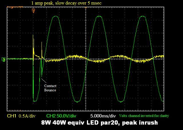
I wanted to set up to test a new 8watt (40w equiv) LED par 20 lamp I purchased recently. I was curious how these new devices might draw their current from the line. While set up I also ran the test you had asked about. I used an very old relay output phase fire unit so excuse the contact bounce.

Here is the inrush at negative peak for the LED bulb:
Only a small inrush and much more linear (but noisy) steady state draw than the CFLs.
8_40WLED05A_div5ms_divinrushatpeakR.jpg


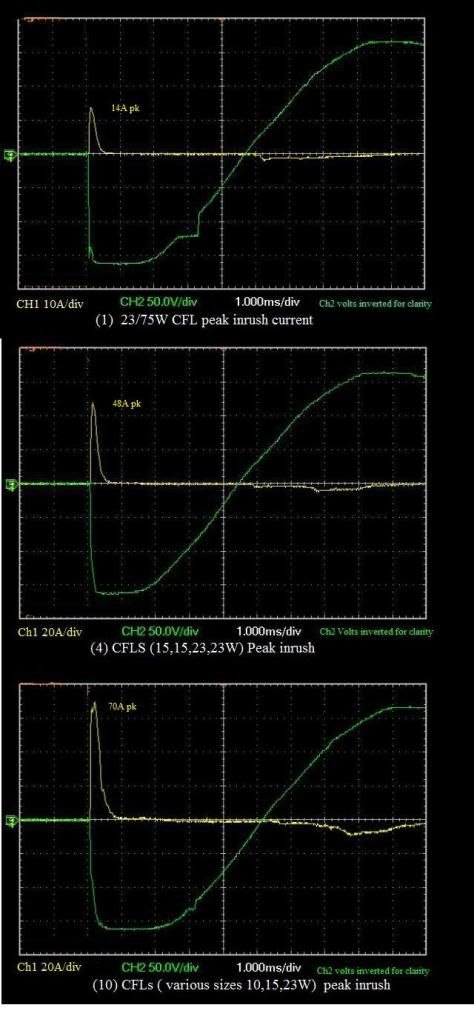
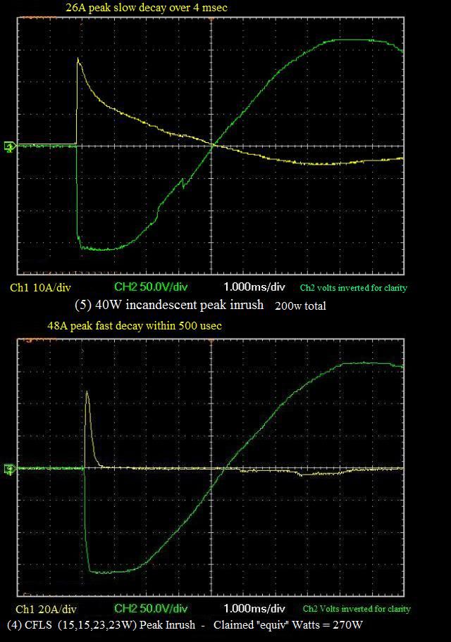
Here is comparison of 1,4 and then (10) CFLs in parallel at negative peak turn on:
CFLINRUSHCOMPARE.jpg


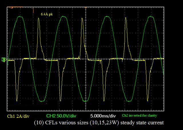
Last is the (10) CFL steady state draw:
10CFLs2A_div5ms_divsteadystatenew.jpg


Cheers!
 

gar

Senior Member
Location
Ann Arbor, Michigan
Occupation
EE
101222-1304 EST

ELA:

Thanks. Definitely a large peak inrush current at the voltage peak. An approximate extrapolation from 10 bulbs to 25 puts the peak about 2.5 * 70 = 175 A.

Looking back at my old posts in this thread I found a mistake where between what my brain intended and what was written do not correlate. I have a high error rate, leaving things out or adding something, that I try to correct by proofreading, but one can not do an effective job of proofreading ones own work.

On a good capacitor the Kill-A-Watt will read 0 for power and current. It's accuracy on voltage isn't to bad. Appears to be monotonic, and thus is great for small voltage difference tests. Therefore useful in measuring voltage drop on a circuit as a load is switched on and off. Useful to measure the length of a wire, or to troubleshoot for high resistance connections, etc.
Wrong it will read 0 for power on a good quality capacitor, but it will read a current of a value based on capacitance, voltage, and frequency.

The illustrate the capability of my Kill-A-Watt I measured an oil filled capacitor the readings were 121.7 V, 0.37 A, 0 W, 44 VA, and 0.01 PF. From this the capacitance calculates to about 8 mfd. Can't read the label but is reasonable for the size. On my General Radio 1650A bridge the capacitor reads 8.0 mfd and D=0.01 at 1 kHz.

.
 

ELA

Senior Member
Occupation
Electrical Test Engineer
101222-1304 EST

ELA:

Thanks. Definitely a large peak inrush current at the voltage peak. An approximate extrapolation from 10 bulbs to 25 puts the peak about 2.5 * 70 = 175 A.

.

Gar,
I would put it <140 amps max best case as a guess. If you compare the (1) to the (4) to the (10) CFLS current peaks you can see that they are additive but not linearly. In addition in a real world there would be distributed inductance (to various bulb locations) to limit some of the peaks.

The more important thing is that the duration of the peaks is very short. I would extrapolate the combined duration of 25 lamps to be less than 1 msec.
Based on these sample tests I do not think there is enough energy present to trip the breaker (although in a best case I would not exclude it totally).

I still think the issue is the nasty current signature on a steady state basis and enough of these causing issues with other sensitive loads. I would still like to experiment with 25 or more CFLs on an AFCI just for fun.

Now that I think about it this may have been the reason, false tripping of AFCI's?
25 lamps would take you over the 5A minimum required for a series arc recognition.

Back to the inrush part of the
discussion. It was from a manufacturers suggestion not to use more than 25 CFLs on a circuit.

This causes me to question:
How many incandescent's would you feel comfortable with on a 20A circuit? For the sake of discussion lets assume 40 watt bulbs. I think I would be more concerned with (25) 40watt or greater incandescents that I would be CFLs in terms of inrush.

I did another test using (5) 40 watt incandescents here for comparison. The incandescents seem to have a more linear additive effect.
Although the incandescents peaks may not be as great their longer duration pulse makes for a greater energy content.

compare4CFLto4IncandescentR.jpg
 
Status
Not open for further replies.
Top