Service Rating

Status
Not open for further replies.

bennie

Esteemed Member
What are the requirements for a disconnect switch to be considered suitable for service equipment?

Does a loadcenter have to be suitable for service equipment after the service disconnect?

Has anyone ever seen a panel that is not suitable for service equipment?

Where does the service equipment end, and the premises system begin?
 

iwire

Moderator
Staff member
Location
Massachusetts
Re: Service Rating

What are the requirements for a disconnect switch to be considered suitable for service equipment?
I do not have a clue, I looked in the UL white book and I did not find anything that helps answer this. :)

Has anyone ever seen a panel that is not suitable for service equipment?
Not that I can remember, all the disconnects seem to come with the obligatory "Service Disconnect" sticker and all the panels seem to say "suitable for use as service equipment.

Where does the service equipment end, and the premises system begin?
Again just my opinion but I would say on the load side of the service disconnect(s)

It would be interesting to know the real answers to these questions. :)

Bob
 

iwire

Moderator
Staff member
Location
Massachusetts
Re: Service Rating

I know you are not a handbook fan Bennie but here is what they say in there.

According to the listing information, panelboards with the neutral factory bonded to the enclosure will be marked ?Suitable Only for Use as Service Equipment.? Other types of equipment intended for optional use, either as service equipment or as sub-distribution panelboards for feeders on the load side of the service disconnect, are required by 230.66 to be marked suitable for use as service equipment. Section 225.36 requires the feeder disconnecting means to be suitable for use as service equipment.
 

bennie

Esteemed Member
Re: Service Rating

Wayne: That is the best site I have ever seen to answer my questions.

On the test, although I got the answer correct, question 17 is not presented correctly.
The question should be; When all circuits are not loaded at the same time, it is called demand factor. All circuits are energized at the same time.

The NEC should have a web site patterned on the Siemens presentation format. There would be no room for controversy on any intent.

My only disagreement with the downstream panel illustration, is the cable, and non-metallic conduit method not being mentioned, as in 408.20.
 

hurk27

Senior Member
Re: Service Rating

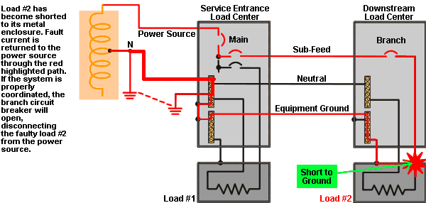
I have a problem With the "Grounding downstream Load centers" When you do a mouse-over it changes to show a fault path short circuit. The problem is the path through the grounding electrodes is dead wrong!

blc3_3_5_r2_c1_f2.gif
 
G

Guest

Guest
Re: Service Rating

Bennie,
I am pleased that you accepted it in the spirit it was offered and that it was actually helpful to you.

When it comes to the NEC-- from reading this forum it is evident to me that the simplest things result in the biggest controversy and the longest (or most heated) discussion threads.
 

bennie

Esteemed Member
Re: Service Rating

Hurk: There will be a portion of fault current from electrode to electrode, I suppose that is the intent of the dotted red line. correct me if you see something I'm missing.

The drawing clearly shows what I have been discussing; Lets call this a 200 amp system. The neutral conductor would be 2/0, the active line is 4/0, the equipment ground conductor is a No.#6. To me, this is not a step forward.

[ October 11, 2003, 10:09 PM: Message edited by: bennie ]
 
G

Guest

Guest
Re: Service Rating

Are you bagging the Siemens original picture because it implies that that Mother Earth is used as a ground fault clearing path? Does this picture look better? The circuit remains the same, but it makes it more clear that Mother Earth cannot be used to clear a fault. Should we contact Siemens about this?

groundfault.gif


[ October 11, 2003, 10:42 PM: Message edited by: awwt ]
 

hurk27

Senior Member
Re: Service Rating

Bennie
The major portion of the fault current would follow the path of the neutral the limiting effect of the high resistance of the grounding electrode would limit the current to a very low value as if the grounding electrode even had a value of 10 ohms and the neutral rose to about 25 volts during the fault above earth potential there would only be about 2.5 amps on it this would add very little in opening the circuit breaker. this is why it should of shown the path at the main panel going to the neutral back to the source as this is what will cause many to believe that the main purpose for the grounding electrode is for fault current which is dead wrong
 

hurk27

Senior Member
Re: Service Rating

Oh the other thing is the reasone you are allowed to just use a #6 to a ground rod is because of the samething as the high resistance of the rod would limit the current even at the full 120 volts that could ever be applyied to it would still be less than 4,8 amps at 25 ohms go down to 10 ohms and it would only be 12 amps so why would it ever need a conductor larger than a #6?
the reasone that it is a #6 is if lightning were to strike the service then because of the short duration of the current the #6 can handle it with out a problem.
 

pierre

Senior Member
Re: Service Rating

The reason or one of the reasons the EGC is permitted to be smaller in size than the Grounded Conductor, is that fault current is intended to flow for a very short duration and the conductor will have (if installed properly) a low enough impedence to allow enough fault current to operate the OCPD, without damage to the system or equipment. The code is the minimum necessary, no one says you cannot run a larger EGC if you should so desire.

Pierre
 

hurk27

Senior Member
Re: Service Rating

Bennie:
I missed the question of EGC on a 200 amp service it would be a #4 copper #3 alu. I was thinking you were talking about the GEC.

[ October 11, 2003, 10:57 PM: Message edited by: hurk27 ]
 

bennie

Esteemed Member
Re: Service Rating

Am I reading the correct chart? 250.66 shows ground electrode conductors for 4/0 is a #4 cu, to a water pipe. 250.122 Equipment ground conductor for 200 amp breaker is a #6 cu.
 

hurk27

Senior Member
Re: Service Rating

Websparky
Look at Table 250.122 Minimum Size Equipment Grounding Conductors for Grounding Raceway and Equipment

and it will show you that a grounding conductor that runs from a disconect to a panel fed by that disconect is allowed to be a #6 this grounding conductor is a EGC and a GEC it serves both.

Grounding Conductor, Equipment. The conductor used to connect the non?current-carrying metal parts of equipment, raceways, and other enclosures to the system grounded conductor, the grounding electrode conductor, or both , at the service equipment or at the source of a separately derived system.

Grounding Electrode Conductor. The conductor used to connect the grounding electrode(s) to the equipment grounding conductor, to the grounded conductor, or to both , at the service, at each building or structure where supplied from a common service, or at the source of a separately derived system.
 
Status
Not open for further replies.
Top