"Single Phase"" From a WYE

Joethemechanic

Senior Member
Location
Hazleton Pa
Occupation
Electro-Mechanical Technician. Industrial machinery
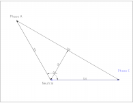
Ok as I am reading the thread I am not getting a clear answer as to the math. I know that phase vectors change things a lot. I'm from philly and very used to working on single, two, and three phase systems,. The diagram below is a 3 wire 2 phase old school Philly transformer secondary. As you can see there are 3 phases available from this connection. As three phase the vectors are nonstandard and we never use the 311 volt phase, but it's still there. For a balanced load on phases 1 and 2 the current on the conductor connected to the 90 degree point will be the current of either phase times the square root of 2 (1.41)

2 phase.jpg
 

wwhitney

Senior Member
Location
Berkeley, CA
Occupation
Retired
Ok as I am reading the thread I am not getting a clear answer as to the math.

Since you're familiar with the 2-phase answer, the diagram below represents 2-phase 3-wire (L1, L2, N) with identical resistive loads L1-N and L2-N. The black represents the voltage phasors, the red the current phasors, and the vector addition is represent graphically by the "tip-to-tail" method. Purple is the sum of the two current vectors, and this shows that the sum is sqrt(2) the magnitude of I1 or I2 (diagonal of a square).

Now, for "2 of 3" phase 3-wire (L1, L2, N), you can apply the same idea to the new geometry, where the L1-N-L2 phase angle is 120 degrees, and you'll find that I1, I2, and I1+I2 form an equilateral triangle, meaning I1+I2 has the same magnitude as I1 or I2. Try drawing it out.

Cheers, Wayne
VectorSum.jpg
 

gar

Senior Member
Location
Ann Arbor, Michigan
Occupation
EE
230626-1450


s_colligan:

In do not understand your post numbered 60.

If you have a wye source and connect three equal resistors, with each resistor from a different line to neutral, then the current at the neutral for each phase is shifted from each other by 120 degrees. These three sine waves cancel each other. If they are not sine waves, then you may not get total cancellation.

.
I agree, and this holds true for inductive and capacitive circuits if they are balanced and linear. It does not hold true if they are non-linear loads and likely they will not cancel out.

In the case a 120v/208v service from a three-phase wye connected source, the 120v and 208v sine waves will be offset by 30 degrees. No? This phase shift comes in when you go from line-to-neutral to line-to-line. Or vice-versa. (Vll = Vln * sqrt(3) @ angle+30 )... delta-wye transform
 

tortuga

Code Historian
Location
Oregon
Occupation
Electrical Design
I when I was a spring chicken I started out in Philly, and there was a lot of Two Phase. And when I accidentally called 208/120 3 wire open wye '2 phase' my boss would say:
 

Attachments

  • open_wye.jpg
    open_wye.jpg
    45.2 KB · Views: 11

Joethemechanic

Senior Member
Location
Hazleton Pa
Occupation
Electro-Mechanical Technician. Industrial machinery

tortuga

Code Historian
Location
Oregon
Occupation
Electrical Design
you can apply the same idea to the new geometry, where the L1-N-L2 phase angle is 120 degrees, and you'll find that I1, I2, and I1+I2 form an equilateral triangle, meaning I1+I2 has the same magnitude as I1 or I2. Try drawing it out.

Cheers, Wayne
Like this?
 

Attachments

  • open_wye.png
    open_wye.png
    36.6 KB · Views: 6

wwhitney

Senior Member
Location
Berkeley, CA
Occupation
Retired
Like this?
More like below, where again the black vectors (from your nice template) are the voltage phasors, the red are the current phases (for a resistive load), and the purple is the sum of two currents. The red-red-purple triangle is supposed to be equilateral, I'm off a little.

Cheers, Wayne

open_wye.jpg
 

tortuga

Code Historian
Location
Oregon
Occupation
Electrical Design
Ahh okay nice thanks now I think i confused myself LOL
So its using

1687837253401.png
With the B phase values being zero (not present).

On a 2 pole 20A breaker connected A-C say a
13 ohm resistor is placed between A and C phases

A phase = 16A , and C phase = 16A
And in open Wye B phase = 0 (Not present)
N works out to 16 Amps.
Yet there is no neutral wire in the circuit?
So is the Neutral current just in the transformer?
 

wwhitney

Senior Member
Location
Berkeley, CA
Occupation
Retired
I don't recall the exact applicability of that formula; IIRC it does apply to 3 resistive loads A-N, B-N, and C-N (and perhaps more broadly), and does not apply in all cases.

In any event, for your 120/208 "open wye" it is worth noting the difference between the (A,B,N) currents being (16, 16, 0) and (16, 16, 16). In the first case, if it's a resistive load connected A-B, then that's 16A * 208V = 3.3 kW of power being delivered. While in the second case, if it's two identical resistive loads connected A-N and B-N, that's 16A * 120V * 2 = 3.6 kW of power being delivered.

In the first case, the current in line A is not in phase with the A-N voltage (likewise for B and B-N), while in the second case, it is. The first case's phase difference is what causes the power transfer to be less, while allowing the current on N to cancel to zero; the second case is represented by the diagram I posted. The diagram you posted gives a decent picture of the first case if you translate (shift, no rotation) the line drawn A-C so that its center is at the origin. Then the two halves of that line represent the two current vectors (which I am drawing in red) in the A and C conductors, and their sum is zero.

Cheers, Wayne
 
Apply KVL around a 3-wire delta: 0 = Va + Vb + Vc ==> Va = -1 * (Vb + Vc)

And multiplying a vector by -1 just rotates it by 180 degrees.

An imbalanced wye transformer will have a neutral voltage which is not at ground potential if the neutral point is not grounded or through a high impedance ground. The imbalance does change the neutral point voltage. If there is a neutral conductor, then neutral currents flow over a low impedance path. If there is not a neutral conductor, then the neutral voltage of the transformer will change in reference to ground. Neutral currents actually do rotate around delta transformers, but not wye transformers. Imbalance shows up as voltage on the neutral point in wye transformers, and rotating current in delta transformers.... generally speaking of course. Harmonics, especially with our new technologies, cause a whole new problem that a lot of times shows up on the neutral.

... getting back to the code... is it a code violation to power a single-phase load from 208Y? Maybe all 208Y/120 service panels are 3-pole? If so, is it code to ensure that loads are properly balanced? Any help is appreciated!
 

tortuga

Code Historian
Location
Oregon
Occupation
Electrical Design
... getting back to the code... is it a code violation to power a single-phase load from 208Y?
There is no code rule against such a circuit. Its used all the time. There are code rules for sizing the neutral when present.
 

Flicker Index

Senior Member
Location
Pac NW
Occupation
Lights
Two legs plus neutral from a wye system is not just commonly called single phase, it is officially called single phase.

IMHO this makes sense because such systems are used to supply exactly the same sort of loads as true single phase 3 wire systems. (Eg. Residential electrical services. )

However OP is quite correct, this is not a true single phase center tapped system in the physics sense, even if it is nominally a single phase system on the official paperwork.

Jon
It is called "single phase" for the sake of simplicity and traditions.

Jeep Cherokee and Nissan Rogue both have four wheels and the trim that is equipped to deliver power to all four of the tires is considered both a 4WD and AWD in a literal sense, but in conversation and marketing, they're not the same.

In literal sense, a three wire service whose L1 to N, and L2 to N voltages are the same but can not be metered correctly on a 2S meter and requires a proper Blondel compliant meter (like 12S) is a "two phase" power.

If you wire up two synchronous alternators in series, put them on a timing chain with the shaft turned exactly 1/2 a turn apart (180 deg out of phase) and run off the same prime mover, the you'll have a so called 120/240 split phase. If you start changing the sprocket position so the rotors are something other than 180 degree apart from each other, you'll see 120-0, 120-0 between L-1, L-2 but L-L will depend on the orientation of the rotors with respect to each other.

Split phase can be likened to a two blade propeller while a 208/120 can be likened to a three blade propeller with one blade broken off.
 

jim dungar

Moderator
Staff member
Location
Wisconsin
Occupation
PE (Retired) - Power Systems
Apply KVL around a 3-wire delta: 0 = Va + Vb + Vc ==> Va = -1 * (Vb + Vc)

And multiplying a vector by -1 just rotates it by 180 degrees.

An imbalanced wye transformer will have a neutral voltage which is not at ground potential if the neutral point is not grounded or through a high impedance ground. The imbalance does change the neutral point voltage. If there is a neutral conductor, then neutral currents flow over a low impedance path.
Ground has nothing to do with voltages.
The neutral point is the important reference point for any analysis of a Wye system.
 
Top