Single phase motor using 2/3 phases

Status
Not open for further replies.

Jpflex

Electrician big leagues
Location
Victorville
Occupation
Electrician commercial and residential
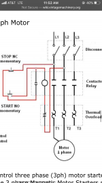
I always wandered about using two phases from a three phase separately derived source (generator). I came across this diagram below which shows 2 phases out of a 3 phase power source being used on a 1 phase motor.

What effect does this have on line voltage seen on motors? Voltage I would not expect to be line x 1.732 as in 3 phase.

But I believe in a 2 phase system voltage would be 2x line voltage because they are 180 degrees out of phase.

However when using 2/3 phases in a 3 phase power source voltage would be 120 degrees out and neither 2x voltage nor 1.732 x voltage. Does this typically yield 208 volts to motor using only 2 phases as mentioned and is this typically how you wire a single phase motor from a 3 phase source?

Feel free to add or comment. Thanks
 

Attachments

  • 298A540F-17D9-4649-B634-8D14B7DBE2B2.png
    298A540F-17D9-4649-B634-8D14B7DBE2B2.png
    707.4 KB · Views: 27
Without trying to address everything you've said/asked, let me comment that a 2-wire load (including motors) doesn't see any notion of phase. It just sees a voltage waveform and cares about the RMS voltage.

You only get a notion of phases when you have more than 2 wires in your supply system. Because a phase shift is a difference in two voltage waveforms, and a voltage waveform comes from a pair of wires, so you'd need at least two different pairs to start talking about phase.

Cheers, Wayne
 
You would only get 208V from a 208/120V Y system. If it was a Delta 240V/120V, you would get 240V. That's excluding the 208V you get on the high leg of the Delta L-N. Using 2 of 3 legs of a 3 ph system makes it single phase.
 
Three phase system voltage is expressed as the line to line voltage. If it’s a wye system, the voltage from each phase to the common wye point is the three phase voltage divided by 1.73.
In your example, the motor is connected between phases, so it sees the line to line system voltage.
 
Three phase system voltage is expressed as the line to line voltage. If it’s a wye system, the voltage from each phase to the common wye point is the three phase voltage divided by 1.73.
In your example, the motor is connected between phases, so it sees the line to line system voltage.
Which brings up another point which I think I asked before. Isnt a 3 phase transformer ampacity typically expressed by the ampacity coming from line to line on 2 phases or are you to add all current from 3 phases line to line as a total?
 
Not a transformer but I meant generator in the above question!
 
The number applied to circuits is the current flow on a single circuit conductor.

A 100A single phase circuit has 100A flowing on 1 circuit conductor and 100A returning on the other.

A 100A three phase circuit has 100A flowing on each of the three circuit conductors.

(well, if running at the circuit rating)

If you have a generator rated for 100A output, you will fully load it with a 100A single phase load (two legs connected to a suitable load), or with a 100A three phase load. (All 3 legs connected to a suitable load.)

The 3 phase 100A load will be drawing more power (greater load on the prime mover) and will produce greater over-all heating in the alternator, but the single phase 100A load will push some components of the alternator to their rated capacity.

-Jon
 
The diagram in your original post is typical of the way you would connect a single phase motor to a 3 phase circuit/starter.
 
You would only get 208V from a 208/120V Y system. If it was a Delta 240V/120V, you would get 240V. That's excluding the 208V you get on the high leg of the Delta L-N. Using 2 of 3 legs of a 3 ph system makes it single phase.
I thought if you were using 2/3 phases it would make it 2 phase. But phases would be 120 degrees off

Then based on what you said, to get 2 phase I assume you would need a generator with 2 separate fields 180 degrees opposed.
 
'Phase' always requires a reference.

If you took two legs plus the neutral from a three phase wye generator you would have 2 phases with a 120 degree phase angle.

But without that neutral you would only have single phase, and it would look like any other two wire single phase source.

Jon
 
I thought if you were using 2/3 phases it would make it 2 phase. But phases would be 120 degrees off

Then based on what you said, to get 2 phase I assume you would need a generator with 2 separate fields 180 degrees opposed.
Bingo. There used to be two phase generation and distribution years ago, particularly in the eastern US. Philadelphia seems to be one common place from what I have read where you still may find some of it still in use. Those systems can be three, four or five wire depending on how the at least 4 source coil leads get interconnected.

That said the phase angle between any two conductors of any system is 180 degrees, and if you have the correct voltage for the single phase item being supplied it will work as designed.
 
As Jon and Kwired point out, if you have only 2 wires of any multi-phase circuit, the phase angle between them can only be 180 degrees.

It can be a bit confusing, but I used to explain this to some young mechanical engineers where I worked using some geometry analogies, which they found useful.

And before I'd start the analogy - I'd remind them that you always need something "else" to measure most things from. Doesn't matter if you are talking about voltage, the length of a 2x4, or your airplane's altitude. That's why your DVM has 2 leads ;)

OK...

Imagine you are standing on a point - like somewhere on a piece of graph paper with X & Y axes.
You can only draw straight lines on this paper.
And you can only "see" (and thereby measure and draw to and from) other points on the graph.
You - and the point you stand on - represent one lead of your voltage system. We'll call you point "A".

Now imagine somebody else (another hot lead of your multiphase voltage system) appears somewhere else on this graph. We'll call this second point "B".
Because you can only see this second point, the only "shape" that you can draw between you both is a straight line from A->B.
You can measure the distance between you both (the voltage potential) along this line, but there really can't be any kind of 3-dimensional shape drawn because there are only 2 points in your universe.

You might want to argue that there are 120 degrees between these 2 points because of where you know they come from (the multi-phase source). But that multi-phase universe, with it's 3rd (and 4th if Wye) wires doesn't exist on your simple graph. All you brought to the paper so far is 2 points.

And as long as there are only 2 points, you are locked into this flat world where you can see only the straight line between you both.
That's the 180 angle that people are saying exists if you have only the 2 wires.

It's physically impossible to measure the 120 degree angle you are thinking about because that angle was measured using a point you don't know about (yet). It has not been brought into your world to measure from. So you can't use it to measure against.

Now, as soon as a 3rd point arrives on this graph, representing another point from a multi-phase voltage system (typically the 3rd phase ("C") - but could be the neutral ("N") from a Wye, it doesn't matter) your world changes completely. It's 3 dimensional!

Now you can draw a triangle, because there are 3 points that don't all "line" up. And you now have the "different pairs" of points that Wayne talked about above... AB, BC, and CA. And now you can start to see, and measure, conventional multi-phase angles, like the 120 degrees you mentioned.

So you need 3 "points" (meaning wires) in your graphical world to create and measure phase angles.
2 wires only gets you that boring straight (180 degree) line.

Not sure if that helps or hurts. Like I said, young mechanical engineers liked it.
 
Now, as soon as a 3rd point arrives on this graph, representing another point from a multi-phase voltage system (typically the 3rd phase ("C") - but could be the neutral ("N") from a Wye, it doesn't matter) your world changes completely. It's 3 dimensional!
Of course, the triangle is really 2 dimensional. 3 dimensional (for 3 phase) was a bad math pun :confused:
 
I would like to thank MD Automation for this analogy! I have struggled with the “phase concept” forever and this actually gives me the view point I’ve needed all along to help understand phase. EXCELLENT POST!
 
tinrat - thanks for the kinds words. And happy to help. I know this stuff is second nature to a ton of people here, but it can be tricky sometimes for others and the graph and lines story helped some young engineers get the idea. I'm glad it helped you too.

The moral - You need to bring more than 2 wires to the party if you want to start measuring angles!
 
The moral - You need to bring more than 2 wires to the party if you want to start measuring angles!
And individual wires/conductors are not 'phases'. Short cuts taken with our language often lead to confusion. Way back when I was in school, it was more common to call conductors as Line 1, Line 2, and Line 3 instead of Phase A, Phase B, and Phase C.
 
Last edited:
And individual wires/conductors are not 'phases'.
Jim, excellent point! Even I goofed on my long post#12 above. I tried hard to talk about "points" and wires (instead of phases), but accidentally mentioned the 3rd phase ("C") near the end :oops:

Referring to the conductors as phases is a lost battle, but it's good to point out it is technically incorrect.
 
Status
Not open for further replies.
Top