mbrooke
Batteries Included
- Location
- United States
- Occupation
- Technician
More out of curiosity then anything else, but how does a single solenoid ATS achieve two switching directions? This has me really intrigued.
I'm pretty sure that they use DC solenoids with a rectifier. Could be they reverse polarity.
Sounds more like an impulse relay (alternating relay) - every time it gets signal to coil it reverses output contact connection. Would need to have some extra logic to determine which state it is in so it doesn't send a signal to the coil to transfer when there is no need to.Most do, but the switching is done at the AC side. One pulse to switch to emergency, one pulse latter for normal. Though I could be wrong on how it happens.
Sounds more like an impulse relay (alternating relay) - every time it gets signal to coil it reverses output contact connection. Would need to have some extra logic to determine which state it is in so it doesn't send a signal to the coil to transfer when there is no need to.
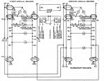
When I think of a single solenoid ATS, GE-Zenith and ASCO come to mind. They both use a single Solenoid with one coil that is fed from a bridge rectifier. It uses an over-toggle cam type of mechanism that switches direction of the main contact closure. On the first pulse from the controller the solenoid plunger pulls in and rotates the cam in the clockwise direction to close contacts to emergency. On the second pulse the plunger pulls in and rotates the cam in the counter-clockwise direction. There is no change in polarity of the voltage to the coil (see attached dwg) The over-toggle action of the cam mechanism is what determines which set of contacts close.
With the GE-Z units this type of design is usually seen on the smaller switches (60-400A)
Two solenoids are used on larger units that pull in to close in to each source.
On the ASCOs the larger units use a single solenoid with (2) coils that are wound opposite to change
direction of the plunger and contact mechanism.
With all ATS manufactures, the standard design is after the unit switches sources, voltage is removed and the contacts are mechanically held closed.
Exactly what I was trying to describe before - there are "alternating relays" and some of the old "touch plate" low voltage lighting relays used similar concept - every time you energize the coil the output changes to opposite state.When I think of a single solenoid ATS, GE-Zenith and ASCO come to mind. They both use a single Solenoid with one coil that is fed from a bridge rectifier. It uses an over-toggle cam type of mechanism that switches direction of the main contact closure. On the first pulse from the controller the solenoid plunger pulls in and rotates the cam in the clockwise direction to close contacts to emergency. On the second pulse the plunger pulls in and rotates the cam in the counter-clockwise direction. There is no change in polarity of the voltage to the coil (see attached dwg) The over-toggle action of the cam mechanism is what determines which set of contacts close.
Exactly what I was trying to describe before - there are "alternating relays" and some of the old "touch plate" low voltage lighting relays used similar concept - every time you energize the coil the output changes to opposite state.
Most "alternating relays" used for things like dual pump stations use an electronic or combination of electronic and mechanical to get the job done, but a purely mechanical alternating relay is exactly what is being described here, it's output contacts change state every time the coil is actuated.
Modern alternating relays for pump stations are not what I am talking about. Those usually are solid state driven even if there is electromechanical components. You lose main power to the solid state component and you may "alternate" the output when power comes back. I recently purchased one that is purely electromechanical, (I believe it was a Tyco/P&B product) and had somewhat at hard time finding what I was looking for. It likely is similar mechanical concept to the ATS solenoids OP is talking about, just smaller in size. Only two coil leads, every time the solenoid operates the mechanism attached alternates which way the double throw switch it drives makes connection.Kwired, I'm very familiar with an alternating relay for equalizing the run times on a dual pump setup and this is not that.
This mechanism is part of the ATS main contact assembly and has no electrical contacts.
Next time you're near a small ATS take a look at the solenoid and the mechanism connected to the plunger to see what I'm trying to describe. If I find a pic I will post it.
Kwired, I'm very familiar with an alternating relay for equalizing the run times on a dual pump setup and this is not that.
This mechanism is part of the ATS main contact assembly and has no electrical contacts.
Next time you're near a small ATS take a look at the solenoid and the mechanism connected to the plunger to see what I'm trying to describe. If I find a pic I will post it.