Sizing a bonding screw

Light Sabre

Member
Location
Colorado
Occupation
Electrical Inspector
Is there a chart that sizes bonding screws somewhere? If you have the right size bonding screw as the main bonding jumper, is this adequate for the GEC to terminate with the EGC bus? Do the manufacturers size these screws for this connection, and if so, from what chart are they being sized? I have some inspectors that say it’s ok to use the bonding screw that comes with the equipment to bond the GC to the EGC, and then terminate the GEC to the EGC bus.
My interpretation is that it has to make the connection using a wire or busbar, and the rest of the items described in 250.28 are out the window. Only a wire or busbar is to make the connection… right? 250.24(A)(4) wouldn’t exist otherwise… right? I have been informed by the inspector that the screws are sized by the manufacturer and adequate, but from what chart?… I need proof! I thought I’d ask here before I ask there. Thanks!
 
If you want to land the GEC on a separate EGC bus then that EGC bus must be connected to the neutral bus via a wire type or bus MBJ. If the MBJ is only a green screw then the GEC cannot terminate on the EGC bus.
 
Is there a chart that sizes bonding screws somewhere? If you have the right size bonding screw as the main bonding jumper, is this adequate for the GEC to terminate with the EGC bus?
I think you have it backwards. The EGC bus is bonded to the GEC (neutral) for the equipment grounds. You wouldn't land the GEC on the EGC bus. As you suspect, that green bonding screw is not capable of handling the full panel current.

-Hal
 
The green screw MBJ would need to carry enough fault current to open the main OCPD if the bus faulted to the metal enclosure. In terms of size the screw is likely going to be smaller than a comparable wire type MBJ.

For example a 200 amp service the bonding screw may be a 10/32 where as a wire type MBJ is going to be #4. If you land the GEC to the EGC bus you're relying on the small screw to connect it to the neutral. If you used a wire type MBJ then it would likely be equal to or larger than the GEC.
 
I thought that these screws had at least 32 threads per inch for that reason. Could be larger than #10 depending on the manufacturer.
The larger ones are clearly not 32 tpi.

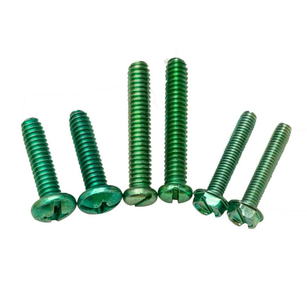
1743186286140.jpeg

From:

Includes:
(2) 1/4-20 x 1 in. pan HD cross recess screws;
(2) 1/4-20 x 1/4 in. pan HD slotted screws;
(2) #10-32 x 1.62 in round HD slotted screws.
 
Because the holes are punctured, not drilled, before they're threaded, so there's more contact area.
Have never seen any factory supplied bonding screw with less than 32 threads per inch other that one that screwed into a bus bar and not the enclosure. However I have not worked with a service panelboard in a few decades. :)
 
I think you have it backwards. The EGC bus is bonded to the GEC (neutral) for the equipment grounds. You wouldn't land the GEC on the EGC bus. As you suspect, that green bonding screw is not capable of handling the full panel current.

-Hal
The GEC is the grounding electrode conductor… the GC is the grounded conductor (neutral)
 
To my interpretation, you can use “bonding screws” for equipment grounds, and to tie the equipment grounds, and ONLY the equipment grounds to the GC. The GEC has to go directly to the GC bus, unless you use a wire or busbar between the two busses… the bond screw the manufacturer sends is only meant for bonding the equipment grounds… not the GEC’s
 
To my interpretation, you can use “bonding screws” for equipment grounds, and to tie the equipment grounds, and ONLY the equipment grounds to the GC. The GEC has to go directly to the GC bus, unless you use a wire or busbar between the two busses… the bond screw the manufacturer sends is only meant for bonding the equipment grounds… not the GEC’s
That's correct. With a screw MBJ the GEC's must go to the neutral bus.
 
So, is there not any chart about how to size “bonding screws” to be as adequate as the wire or busbar connections mentioned in 250.24(A)(4)?… should I maybe ask a manufacturer about this?… the inspector says he has done the research, and the screw is adequate. I still need proof from what chart? From what table? How are the manufacturers sizing these without NEC standards in place? Oof
 
should I maybe ask a manufacturer about this?… the inspector says he has done the research, and the screw is adequate
The NEC doesn't tell you what size the screw used as a MBJ must be. It's likely part of the UL listing where it must be tested using certain parameters. The screw that comes with the panel is adequate as the MBJ. It is not adequate to allow the GEC to be connected to the EGC bus.
 
Are you saying the bonding screw from the manufacturer is sized to be a main bonding jumper? Where and how are they sizing this… is there a chart? If so, why does article 250.24(A)(4) exist?
I'm saying that's by far the most common size I have seen and installed in 200a disconnects and MB panels over the decades, maybe a few hundred.

Sometimes it only bonds the enclosure, sometimes the EGCs and the enclosure, but it should never be part of the neutral current nor GEC pathways.
 
So, is there not any chart about how to size “bonding screws” to be as adequate as the wire or busbar connections mentioned in 250.24(A)(4)?… should I maybe ask a manufacturer about this?… the inspector says he has done the research, and the screw is adequate. I still need proof from what chart? From what table? How are the manufacturers sizing these without NEC standards in place?
I am claiming absolutely nothing toward what manufacturers depend on to choose bond-screw sizing.

I would guess they use a specific amount of current for a specific duration resulting in no damage.
 
Top