Wondering the right way to model this, I was told that the relay must be placed in a way so that it can open/close the switch, otherwise it's just a passive device.
But I don't know what that means in context of my model exactly.
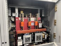
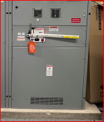
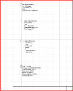
Is this correct (snapshot of SKM below)? I placed the relay after the switch and before the fuse, which is how it seems to be in the actual switchboard. The switchboard in real life has an incoming line-side connection, feeding the switch, which appears to feed the fuse, which then appears to feed the switchboard bus. The relays appear to sit in between the fuse and switch.
But I don't know what that means in context of my model exactly.
Is this correct (snapshot of SKM below)? I placed the relay after the switch and before the fuse, which is how it seems to be in the actual switchboard. The switchboard in real life has an incoming line-side connection, feeding the switch, which appears to feed the fuse, which then appears to feed the switchboard bus. The relays appear to sit in between the fuse and switch.