You are using an out of date browser. It may not display this or other websites correctly.
You should upgrade or use an alternative browser.
You should upgrade or use an alternative browser.
So where does extra current go with bad distortion PF (Standard VFD input)?
- Thread starter mike_kilroy
- Start date
- Status
- Not open for further replies.
")
gar
Senior Member
- Location
- Ann Arbor, Michigan
- Occupation
- EE
170708-1442 EDT
Sahib:
In post #85 I explained it.
Just eliminate your VFD's DC to AC conversion and put your resistive load on the DC filter bank, and assume the ripple is small. Further assume that between the AC line and the filter capacitors we only have diodes. Also assume single phase input for simplicity. This makes the whole circuit simple.
Power in the resistor is Vdc*Idc. Idc must equal Iac ave (full wave recdtified) at the input side of the diodes. Assume the AC source voltage is a sine wave, then Vac rms = 0.707 * Vdc, or Vdc = 1.414*Vac rms.
Note: at the resistor that Vdc = Vrms measured across the resistor, and that Idc = Irms thru the resistor. Both Vdc and Idc are constant values because the capacitor ripple is low. If you place both a DC meter and an AC electrodynamometer meter across a DC voltage source both read the same value.
If the AC current into the diode rectifier was a sine wave (which it is not), then Iac rms would have to equal
Vdc*Idc = 1.414*Vac rms*Idc
Idc = Iac ave
Iac rms = (0.707/0.636)*Iac ave = 1.112*Idc
Vdc*Idc = 1.414*Vac rms*Iac rms/1.112
Vdc*Idc = 1.272*Vac rms*Iac rms (power in has to equal power out in a lossless system which we will assume is true for the diodes and capacitor)
But the AC current is nothing like a sine wave, it is more peaked and thus its RMS value is greater.
Average charge flow on both sides of the rectifier has to be the same, but RMS currents don't have to be the same. Where does the RMS current go --- somewhere in the mathematical world.
.
mike_kilroy
Senior Member
- Location
- United States
170708-1442 EDT
Sahib:
In post #85 I explained it.
Just eliminate your VFD's DC to AC conversion and put your resistive load on the DC filter bank, and assume the ripple is small. Further assume that between the AC line and the filter capacitors we only have diodes. Also assume single phase input for simplicity. This makes the whole circuit simple.
Power in the resistor is Vdc*Idc. Idc must equal Iac ave (full wave recdtified) at the input side of the diodes. Assume the AC source voltage is a sine wave, then Vac rms = 0.707 * Vdc, or Vdc = 1.414*Vac rms.
Note: at the resistor that Vdc = Vrms measured across the resistor, and that Idc = Irms thru the resistor. Both Vdc and Idc are constant values because the capacitor ripple is low. If you place both a DC meter and an AC electrodynamometer meter across a DC voltage source both read the same value.
If the AC current into the diode rectifier was a sine wave (which it is not), then Iac rms would have to equal
Vdc*Idc = 1.414*Vac rms*Idc
Idc = Iac ave
Iac rms = (0.707/0.636)*Iac ave = 1.112*Idc
Vdc*Idc = 1.414*Vac rms*Iac rms/1.112
Vdc*Idc = 1.272*Vac rms*Iac rms (power in has to equal power out in a lossless system which we will assume is true for the diodes and capacitor)
But the AC current is nothing like a sine wave, it is more peaked and thus its RMS value is greater.
Average charge flow on both sides of the rectifier has to be the same, but RMS currents don't have to be the same. Where does the RMS current go --- somewhere in the mathematical world.
.
I had tried to show you the reactive current on the vfd output had zero meaning or effect on the ac input current; you would not see that. So be it.
Sahib did good changing my example to a purely resistive load; now you see my point. So far, Sahib sees my point, gar said thanks for bringing the concept up so he sees it some, and this last post of yours actually gets you close to understanding the point of OP.
Although you still do not seem to grasp distortion pf totally, you are close when you can write: But the AC current is nothing like a sine wave, it is more peaked and thus its RMS value is greater.
Average charge flow on both sides of the rectifier has to be the same, but RMS currents don't have to be the same. Where does the RMS current go --- somewhere in the mathematical world.
THAT was the reason for my OP.
Most people blindly believe that since the input current to a vfd is in phase (only supplying the torque producing Isq current to the motor), the input PF is basically 1.0 - and TOTALLY ignore the distortion PF that can cause the ac input RMS current to be 2-3 times HIGHER than the output in phase current. Of course the average input current is going to equal the average output Isq current into the motor - that is ol' power in equals power out.
How bad the input distortion PF is is a function of the Z of the input power source. The same exact vfd/motor/load can have a .5 distortion PF at one customer and .9 at another across town. THIS was my point of thread. I was trying to bring up the fact that AC RMS input current is useless figure to use in most cases and why.
mike_kilroy
Senior Member
- Location
- United States
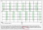
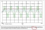
I won't post the link to the whole Schneider Electric article because doing so will probably just cause more off topic confusion. But here are 3 input current scope pix and corresponding Irms values for identical vfd/motor/load. Clearly shows Irms input of 6 to 16amps rms for the same thing.
We COULD go on and discuss how the many comments that current into unlinear load of diodes is not calculable or the extra heat is easily shown with this Irms (it is not just a mathematical figure), but I am afraid to do so. Prob best to leave this thread here.
We COULD go on and discuss how the many comments that current into unlinear load of diodes is not calculable or the extra heat is easily shown with this Irms (it is not just a mathematical figure), but I am afraid to do so. Prob best to leave this thread here.
Attachments

gar
Senior Member
- Location
- Ann Arbor, Michigan
- Occupation
- EE
170708-1951EDT
mike_kilroy:
I have never said or implied that the input power factor to a VFD was unity.
In post #308 I showed the current input to an actual VFD on a HAAS CNC mill. There is no way this power factor is close to unity.
Numerous persons have mentioned VFDs with unity input power factor. There have been no waveforms shown to the best of my memory. I expect that there are VFDs with good input power factors, and I expect that the government will be forcing manufacturers to supply equipment with better input power factor.
Following are the results of an experiment to show that the sum of the output RMS currents from a point may not equal the input current to that point.
The experiment consists of a 125 V 60 Hz line source from a Variac. The loads are a 25 W incandescent (pure resistance), and my full wave center tapped DC supply with a large filter capacitor load with a 5 ohm resistor and low ripple. Power supply input has substantial current peaks, and PF is not 1, but around 0.72.
Using RMS current measurement:
92.8 W 0.89 A 0.83 PF -- total
26.5 W 0.21 A 1.__ PF -- 25 W bulb
66.4 W 0.74 A 0.72 PF -- DC supply
92.9 W 0.95 A 0.78 PF -- summing the two individual loads
Measured total RMS current, 0.89, is quite different from the sum, 0.95, of the individual RMS currents.
Using a Fluke 27 current measurement (average reading, not RMS):
92.8 W 0.71 A -- total
26.5 W 0.21 A -- 25 W bulb
66.4 W 0.51 A -- DC supply
92.9 W 0.72 A -- summing the two individual loads
Measured total average,0.71, is quite close to the sum of the individual average currents, 0.72 . Here we are measuring charge flow.
.
mike_kilroy
Senior Member
- Location
- United States
170708-1951EDT
mike_kilroy: I have never said or implied that the input power factor to a VFD was unity.
.
Gar I apologize; my post questioning some most recent comments was NOT directed to you as it sounded.
Pf on the input is not based on the VFD
Pf on the input is not based on the VFD
What a great discussion! So, I pondered this for a bit and based on the info given:
Input: 460 vac 3-phase 60hz at 12 amps
Output: 460 vac 3-phase 60hz at 6 amps
I agree that the input power factor is likely at 0.5 or less, depending on the pf on the VFD output which is likely around 0.9pf to the motor. The fact that this 460vac power is supplying a VFD doesn't effect the pf, just doesn't add or subtract from it much. The adjacent 460 volt motors and transformers being fed from the same transformer secondary are clearly not using VFDs, hence, low power factor on the 460 volt feeder, which feeds the VFD. This would explain the resulting high amps on the VFD input as compared to the lower amps on the output due to the lower power factor of 0.9 going to the motor. This meets the basic physics of power in equals power out x efficiency. I have not seen this much of a mismatch on VFD installations, but the mismatch is there and the question is valid, where do the amps go. They are lost as "watt-less power" as are the amps with any lower pf system installation. Power lost is the I^2 R losses from the additional amps, which go off as heat in the conductors and chokes. The chokes are there more for protection of the rectifier circuits than for power factor correction, but they likely do both. No magic box in VFDs, even though the low voltage drop on the IGBTs still amazes me. Battery charger on one end used to charge the capacitors and a three phase inverter on the other providing exceptionally clean AC power.
Pf on the input is not based on the VFD
Wrong.
Of course, but irrelevant to this discussion. I specifically said ignore output of vfd for good reason
Sent from my SM-G900V using Tapatalk
What a great discussion! So, I pondered this for a bit and based on the info given:
Input: 460 vac 3-phase 60hz at 12 amps
Output: 460 vac 3-phase 60hz at 6 amps
I agree that the input power factor is likely at 0.5 or less, depending on the pf on the VFD output which is likely around 0.9pf to the motor. The fact that this 460vac power is supplying a VFD doesn't effect the pf, just doesn't add or subtract from it much. The adjacent 460 volt motors and transformers being fed from the same transformer secondary are clearly not using VFDs, hence, low power factor on the 460 volt feeder, which feeds the VFD. This would explain the resulting high amps on the VFD input as compared to the lower amps on the output due to the lower power factor of 0.9 going to the motor. This meets the basic physics of power in equals power out x efficiency. I have not seen this much of a mismatch on VFD installations, but the mismatch is there and the question is valid, where do the amps go. They are lost as "watt-less power" as are the amps with any lower pf system installation. Power lost is the I^2 R losses from the additional amps, which go off as heat in the conductors and chokes. The chokes are there more for protection of the rectifier circuits than for power factor correction, but they likely do both. No magic box in VFDs, even though the low voltage drop on the IGBTs still amazes me. Battery charger on one end used to charge the capacitors and a three phase inverter on the other providing exceptionally clean AC power.
- Status
- Not open for further replies.