Okay, the day is winding down here. Thanks for the brief vacations; this is an interesting puzzle to look at.
Bcorbin, that is not how harmonic analysis works. Once you have a square wave, you have a square wave, and it doesn't matter how it was generated, the harmonic content is the same.
Part of the confusion (my own included) is that we keep saying 'the voltage', rather than remembering that with the circuit as described there are several different voltages to consider. If we don't specify which two points we are measuring the voltage between, then the value of the voltage is meaningless.
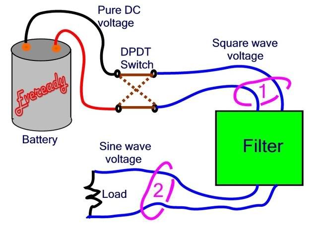
Consider the circuit as drawn by crossman. The filter is as defined by rattus; infinite impedance to any of the harmonics, zero impedance to fundamental. The voltage at the two input terminals to the filter is a square wave, and the instantaneous voltage across this filter is either +Vb or -Vb (depending upon where in the cycle you are and how you select your terminals). The voltage across the resistor is a sine wave, with a peak value of +-4/pi*Vb
Nothing has been magically created; this is the nature of the filter. Even though the filter is 'ideal' and 'lossless', by the definition of its frequency response it must be storing some energy.
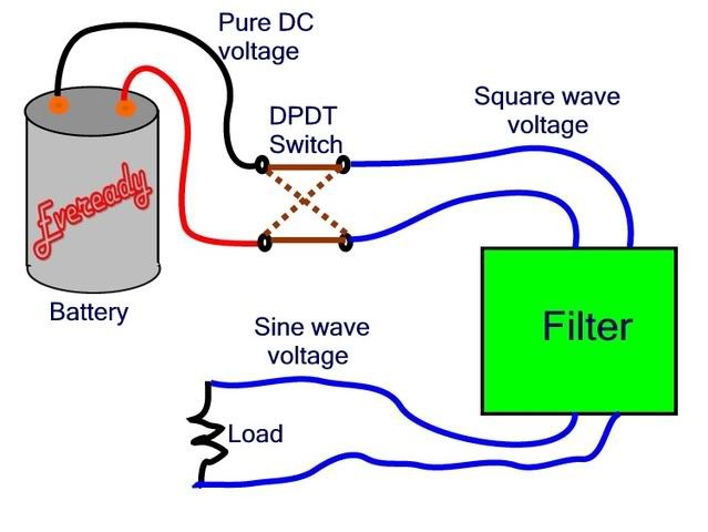
Rather than considering an ideal filter, lets instead consider a circuit built with real components. Use the same battery and DPDT switcher. But now instead of an ideal filter, have a simple capacitor and resistor.
Start with the capacitor discharged, and turn everything on. The capacitor starts charging up, just like any RC circuit connected to a battery Suppose the period of the square wave is much longer than the RC time constant. The capacitor essentially charges all the way up to Vb and current flow falls to zero. But then the switch toggles, and for a moment the voltage across the resistor is 2*Vb.
The capacitor in series with the resistor is a high pass filter, and the spiky waveform with 2*Vb peaks is the high frequency component of the square wave.
crossman, in your second diagram, assuming ideal components, the _average_ power at location 1 and location 2 is equal. The _instantaneous_ power will be unequal, but which is greater will alternate, I believe at 2x the square wave frequency.
Oh, for a fun one to consider, imagine a circuit consisting of an inductor, a capacitor, and a resistor, all in series and supplied by 120V 60Hz. The resistor has a value of 120 ohms. The inductor and capacitor are selected to have a 60Hz impedance of 600 ohms each. What is the current through the circuit, and what is the voltage across the inductor?
-Jon
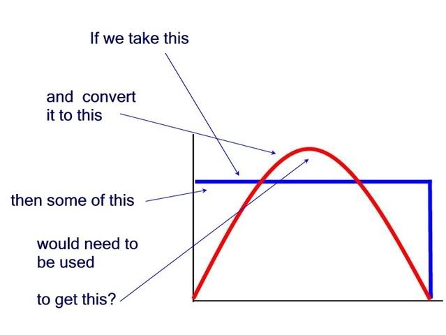
") The peak voltage of the fundamental component of the a square wave is greater than the peak voltage of the source square wave.
The peak voltage of the fundamental component of the a square wave is greater than the peak voltage of the source square wave.