To tap into the existing piece of 14/2 UF cable midstream I am thinking about soldering a new piece of 14/2 UF onto it. I have never soldered anything larger than perhaps 18 gauge. Is there a downside to soldering 14 gauge wire in a trench? Any time that I have run across soldered splices in older homes I have been impressed with the splice. If I go this route I do not have to cut the existing cable which means a second splice kit.
Thanks,,,,
You can solder even copper pipe but solder is just metallic glue...actually really just metallic filler. It has ZERO mechanical strength. You ALWAYS must mechanically secure connections if there is any force at all on them whether they are soldered or not. On circuit boards all it does is fill in gaps so the parts don’t just fall off. It only works in plumbing because the pipe is very tightly fit already and solder filler makes it an interference fit and blocks up gaps so water does not leak.
The old original way to connect wires was to twist both wires against themselves in a telegraphers knot then cover the thing in solder. The knot is the key though. It works just as good without the solder. Soldered wiring always has some kind of tie or tight fit. It is physically a very small connection (test sockets for surface mount chips cost hundreds!) But outside of very low power connections with zero vibration or mechanical stress it is terrible.
The practice of soldering everything stayed around until cars started having tons of electronics and the higher current higher vibration started causing failures. I mean some of those 1940s and 1950s cars were in the shop 6 months after they were sold. Auto manufacturers eventually realized through testing that solder not only doesn’t have any mechanical strength but it stiffens the copper wire even up under the insulation and makes it brittle and easier to break! Soldered connections were banned from use in automotive plants in the 1970s.
This ushered in the era of both crimped lugs and mechanical lugs and connectors that were solderless in the 1960s and 1970s. It took about a generation for electricians to get retrained to stop gobbing up everything with solder.
Even today in power circuits solder lives on as a huge issue. In high power electronics for drives (VFDs), solder joints fail after 10-15 years. No research on alternative alloys or techniques has found a solution. In utility and locomotive applications Semikron produces parts which are welded together (sintered). Although some OEMs persist in trying to solder motor connections, virtually all rewind shops use crimped or welded (TIG) connections.
So getting back to your use. Even in the South where frost is not around, Earth moves. Even if it didn’t electrical wiring vibrates especially when a motor or transformer starts. Plus you have water to contend with. There are special insulated terminal blocks for this. One brand name is “Insultap”. They are made by Polaris, Burndy, T&B, Ilsco, and others. Any electrical distributor usually has some in various shapes and sizes and port counts. You can get waterproof wire nuts too but I’ve had less issues with the insulated terminals for this use.
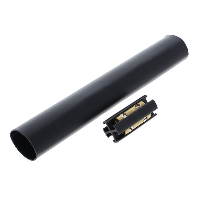
If you truly want to go old school and have the tools, go old school. Get adhesive lined heavy wall shrink tubing. Cut wiring so phases don’t overlap. Crimp on ring terminals. Put on the tubing BEFORE the next step. Put one piece on each set of individual wires and one over the whole jacket. Bolt everything together. Then slide the smaller tubes over the bolts and lugs. Shrink it on. Now slide the outer jacket tube over all of it and shrink it on.
Somewhat less old school is the same as above but doing a taped connection. The advantage is you can buy everything you need at Home Depot. First crimp on ring terminals or use mechanical lugs. Then bolt everything together. Then the next step is 3M calls for varnished cambric which is the one tape you won’t find at big Orange. Use Scotch Fill if you can find it to build up around the bolt and any “valleys”. Then wrap 88 (preferred) or 33+ while stretching it to about half thickness in half wraps until you have at least two layers but also make sure you cover every single metal surface and have enough tape to cover any sharp edges. Now wrap in 130C rubber splicing tape. Fill up any valleys so it is nice and smooth. At least two layers of half wraps but use minimal stretch on this stuff. You want to avoid any air pockets on every layer but you want the 130C to be thick. When you put on the power this stuff is going to melt and form a waterproof single layer jacket. Finally do two more layers of half wraps of 33+ or 88. On the first layer stretch it a little but on the final layer don’t stretch it a lot. The stretching puts tension in the tape so that it pulls on itself and keeps the 130C from dripping and leaking out but on the last layer it can cause flagging (end unwraps itself) so minimize stretching.
3M has YouTube videos on the procedure if you search for taped motor terminations. American Electricians handbook has similar procedures using the tape or heat shrink method for every kind of cable. In most of them the goal is to have about 150% more insulation than the original cable followed by an outer waterproof and abrasion resistant jacket. I can attest to both the taping and heat shrink methods. I’ve used both on 480 V #6 SOOW cord on a shore power system on a dredge. The tape and heat shrink methods both work even under water with sand and ice but it takes an hour to tape properly and 20 minutes to heat shrink a splice.