Not all services have neutrals. E.g. a 3P3W service.
The requirements under discussion are the confluence of several different factors. First, suppose we didn't have to worry about electrical faults (we have a magic genie watching over the system who will intervene to prevent any current from leaving the circuit conductors). We'd probably still want to bond together all the exposed metal parts that aren't circuit conductors, just because of the possibility of potential differences due to static, inductive or capacitive coupling with the circuit conductors, lightning, etc. And since we could plausibly be in contact with those bonded metal parts and with the earth (or something conductive in contact with the earth), we'd want to bond those metal parts to the earth as well--that's the role of the grounding electrode system and grounding electrode conductor.
So let's take that level of bonding as a minimum starting point. If you want, for some voltage systems you can operate your electrical system that way, and we call it an ungrounded system. If you have a fault from one of the circuit conductors to the bonded/earth metal parts (a ground fault), the system will still function fine. It would take a second ground fault from one of the other circuit conductors to cause fault current to flow. In such a system you are required to monitor for the first ground fault, and when it happens you are supposed to fix that ground fault before the second one can occur.
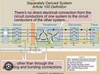
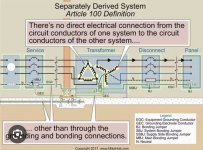
The other strategy is to pick one of the circuit conductors and intentionally make that first fault in one known location. That would be the MBJ (for a service) or SBJ (for an SDS). We call that circuit conductor the grounded circuit conductor, and we call this a grounded system. The grounded conductor has some special rules, for example it doesn't require OCPD. So this is the configuration you are likely most familiar with.
When the voltage system has a neutral, then by convention (and for a few other reasons), we choose the neutral conductor to be our grounded conductor. But if you have, say, a 240V 3P3W system, you have a choice to either run it ungrounded, or to ground one of the 3 conductors. The latter is referred to as corner grounded, since our grounded conductor is not a neutral.
Cheers, Wayne
")