Stepper motor help (off topic... sorry ) an "Other Stuff" category would be nice

Status
Not open for further replies.

realolman

Senior Member
Stepper motor help (off topic... sorry ) an "Other Stuff" category would be nice

I would like to operate a component of a machine that contains a stepper motor on the test bench, for the puposes of adjustment and repair. I feel sure the OEM would frown upon this activity, so I don't think I could get much help from them.

I have an Oriental brand bipolar stepper motor with 4.5 ohms per winding. It is connected to a Sanken A2918SW motor driver. If anyone is interested the documentation is at :

www.allegromicro.com/en/products/categories/Sanken/Motor_Drivers/Motor_Driver_ICs_h1-i02eb0.pdf

There is not as much info on this model as others. I have disconnected the stepper driver board from the rest of the component, and am enabling and phasing it with a BASIC STAMP according to the truth table on the documentation. I think I have the sequence correct because I have tried all the combinations I can think of and this one seems to be the best.

The problem is it doesn't seem to have as much torque as it should.


stepperdriver.jpg


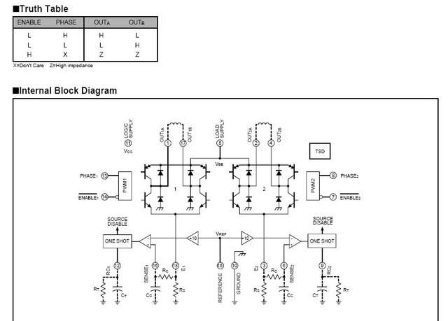
VBB > Vref = 39VDC, and I am using enable ,1 enable 2, and phase 1, and phase 2 . It seems to me from looking at this drawing that I should have something hooked to E1 and E2, but I don't ... should I have something hooked to E1 and E2...any suggestions on the resistor values?

thanks
 

mxslick

Senior Member
Location
SE Idaho
Hope this helps...

Hope this helps...

I work with film dubber units that use stepper motors..and as far as I can tell from the diagram and truth table you posted:

It appears that for each "side" of the drive, BOTH enables need to be maintained low to make it run, and the status of the PHASES need to be in opposite states at the desired pulse rate. When phase 1 is high, 2 must be low and vice-versa.

The direction of rotation would (should) depend on which Phase in leading in the pulse sequence.

It is important (at least in my experience with dubbers) that the phase drive be a clean square wave, sequenced 90 degrees apart, and be as close to the same timing and voltage as possible. Any errors or asymmetry of the pulse train will reduce torque or cause speed errors.
 

ELA

Senior Member
Occupation
Electrical Test Engineer
realolman,

It has been a while since I worked with these but here is a thought.

It looks like you do need to have current sense resistors connected to E1 and E2 as you mentioned. The data sheets tell how to determine the values.

Look at page 9.

These are also often controlled with a constant current chopper method as explained on pg. 5.

The recommended external hookup is shown on pg. 7.

I suspect you have more connections required?

Its been too long for me to be more direct help without spending a lot of time.

Hope that helps some.
 

realolman

Senior Member
Hey thanks a lot... you bet it will help.

My main problem was that I googled the part number off the chip A2918SW and all that returned was a 68 page data sheet that contained several other models. This particular model had almost zero info, except for a couple drawings.

Later I discovered that search for Allegro A2918 results in a much more detailed data sheet... must be the one you have.

I will press on, using your advice, and the new data sheet.... thank you very much for your response.:smile:

Edited... actually mine only has 8 pages. would you be so kind as to provide a link to where you got yours. thanks
 

ELA

Senior Member
Occupation
Electrical Test Engineer
realolman said:
Hey thanks a lot... you bet it will help.

My main problem was that I googled the part number off the chip A2918SW and all that returned was a 68 page data sheet that contained several other models. This particular model had almost zero info, except for a couple drawings.

Later I discovered that search for Allegro A2918 results in a much more detailed data sheet... must be the one you have.

I will press on, using your advice, and the new data sheet.... thank you very much for your response.:smile:

Edited... actually mine only has 8 pages. would you be so kind as to provide a link to where you got yours. thanks

Must be something strange going on? I used the link you provided and I got 114 pages.

I thought about this a little more and am guessing that your current limit resistors need to be connected to complete the current chopper circuit. This produces the fast rise time current waveforms required for maximum torque.

Have fun
 

realolman

Senior Member
You are correct. that link has a big document. Most of the info is about other models... there is practically nothing about the a2918.

I thought the stuff to which you referred pertained to the unipolar drivers.

They sure don't make nuthin easy.:smile:

I found another document that is all about this particular model.

I don't expect you to put anymore effort into this. I already appreciate what you've done... but just in case you're interested here's a link that has a much better datasheet for this model:

http://www.allegromicro.com/en/Products/Part_Numbers/Archive/2918.pdf

thanks ... it is kinda fun.... in a masochistic sorta way.
 

ELA

Senior Member
Occupation
Electrical Test Engineer
The same concepts apply. They do have a better explanation of the chopper current limit there and the importance of the current limit sense resistors.

Good Luck
 
Status
Not open for further replies.
Top