Strobing LEDs correlate to tankless water heater operation.

11bgrunt

Pragmatist
Location
TEXAS
Occupation
Electric Utility Reliability Coordinator
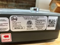
A recent complaint was focused on the LED fixtures in the house began strobing when the Rheem 13kW tankless water heater in the shop came on.

This is an off the shelf tankless from Home Depot for $300.
All is new construction.
After extensive testing in the shop and in the house, the tankless water heater seems to be the only issue.
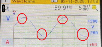
There was a voltage transient that appeared only when the tankless water heater was powered on.
The THDV increased slightly when the tankless was on, but we never saw more than 2.3 THDV.

I assumed the tankless used an element similar to a conventional stored water heater.
Can anyone shed light on this? I suggested the customer to contact the manufacture.
 

Attachments

  • Waveform.PNG
    Waveform.PNG
    996.3 KB · Views: 24
  • dataplate.JPG
    dataplate.JPG
    115.2 KB · Views: 23
Cheaper LED's don't like voltage fluctuations or wave distortions. I can see a tankless contributing to both issues. Even if you ran pretty heavy supply lines, POCO may still have undersized transformer causing voltage drop when heavy load like this is running. I can also see them having solid state switching controls vs dry contacts for control which could cause distortions on waveforms.
 
The POCO transformer is 37.5 kVA. Another 50A steamer load tested, did not have the same effect. There is no visible voltage sag on HVAC start.
 
Electric tankless water heaters use scr’s to control the temperature output of the elements.
The voltage drop would probably to quick for a standard multi meter to detect.
 
I agree: the scope is picking up voltage transients that are related to the water heater SCRs switching.

I think that you can reliably confirm that these transients are coming from the water heater as follows: My _guess_ is that if you operate the water heater and change the setpoint temperature (thus changing power level and trigger time of the SCRs) that the voltage transients will move to different parts of the AC cycle.

What is probably happening is that these _tiny_ voltage transients are being picked up by the part of the LED driver circuit that is supposed to detect dimming waveforms, and then the LED driver circuit is varying the LED drive current. Bang: everything flickers.

A solution might be a suitably rated common mode noise filter on the water heater circuit.

-Jonathan
 
Even though the water heater is applying a line-to-line load, I suggest measuring the L1-N and L2-N waveforms with your scope if you haven't already done so, since that is what the lights are being supplied with. That's just to make sure there isn't something going on with the neutral that could be relevant.
 
Here is a photo I found online of the guts of one of the Rheem RTEX-13, you can see it has two elements switched by what look to be two Silicon Controlled Rectifier's (SCR's). It would be interesting to see exactly what those chips these are.
As I under stand SCR's are either on or off.
You can see them the left and look to be cooled by the incoming cold water.

1771347493754.png
Looks like two elements so each element is ~6.5kW or 27 amps,
I am curious how the controller times when in the AC sine wave the SCR turns on?
I'd imagine it cycles the SCR on and off ramping up with a flow meter similar to Leading Edge (MLV) dimming,
my guess is those rapid load transitions is a unique load of 1/3 of the transformers nameplate, are causing changes in voltage that confuse LEDS that are trying to be 'dimmable'.
I wonder if a line capacitor would smooth that out, probably not cost effective.
 
Here is a photo I found online of the guts of one of the Rheem RTEX-13, you can see it has two elements switched by what look to be two Silicon Controlled Rectifier's (SCR's). It would be interesting to see exactly what those chips these are.
As I under stand SCR's are either on or off.
You can see them the left and look to be cooled by the incoming cold water.

View attachment 2582070
Looks like two elements so each element is ~6.5kW or 27 amps,
I am curious how the controller times when in the AC sine wave the SCR turns on?
I'd imagine it cycles the SCR on and off ramping up with a flow meter similar to Leading Edge (MLV) dimming,
my guess is those rapid load transitions is a unique load of 1/3 of the transformers nameplate, are causing changes in voltage that confuse LEDS that are trying to be 'dimmable'.
I wonder if a line capacitor would smooth that out, probably not cost effective.
That is correct, there is a flow switch that cuts it on, with a temperature sensor that lets the processor know the rate the scr needs to turn on. The first one’s built were on or off, so the temperature would change depending on the flow. Later, especially with the gas ones, it was regulated by temperature by increasing the flame, or increasing the time the element was on.
 
Here is a photo I found online of the guts of one of the Rheem RTEX-13, you can see it has two elements switched by what look to be two Silicon Controlled Rectifier's (SCR's). It would be interesting to see exactly what those chips these are.
As I under stand SCR's are either on or off.
You can see them the left and look to be cooled by the incoming cold water.

View attachment 2582070
Looks like two elements so each element is ~6.5kW or 27 amps,
I am curious how the controller times when in the AC sine wave the SCR turns on?
I'd imagine it cycles the SCR on and off ramping up with a flow meter similar to Leading Edge (MLV) dimming,
my guess is those rapid load transitions is a unique load of 1/3 of the transformers nameplate, are causing changes in voltage that confuse LEDS that are trying to be 'dimmable'.
I wonder if a line capacitor would smooth that out, probably not cost effective.
Might be they possibly shave peaks of current waveform to more precisely control heat output? Might only show up as a minor distortion to the input voltage wave like we see in OP, especially if measuring at/near the unit. Would be nice to see what current waveform looks like as well.
 
...
I am curious how the controller times when in the AC sine wave the SCR turns on?
I'd imagine it cycles the SCR on and off ramping up with a flow meter similar to Leading Edge (MLV) dimming,
my guess is those rapid load transitions is a unique load of 1/3 of the transformers nameplate, are causing changes in voltage that confuse LEDS that are trying to be 'dimmable'.
I wonder if a line capacitor would smooth that out, probably not cost effective.

Yes, I believe that the triacs are under "phase control" just like leading edge dimmers operate. As winnie mentioned above, the time within each AC half cycle where they turn on will likely move as the temperature set point is changed, or with the flow rate. I think the notching in the voltage is not primarily from any peak in the current drawn, but from the initial voltage drop across the inductive reactance of the distribution transformer when the triac turns on. If there is another house on the transformer perhaps their LED lights could also be affected.

Although it's possible that an L- C lowpass filter inline with the water heater could smooth out the voltage drop, I think it would be fairly large and costly. If the strobing effect is limited to a few lights, an L-C filter might be more practical on those lower power circuits. If the lights are on dimmers, using a dimmer with a neutral connection (if not already present) or another type of dimmer might help.
 
Might be they possibly shave peaks of current waveform to more precisely control heat output? Might only show up as a minor distortion to the input voltage wave like we see in OP, especially if measuring at/near the unit. Would be nice to see what current waveform looks like as well.

As @synchro describes, the SCRs (also called triacs) use 'phase control' to adjust the RMS voltage and thus the RMS current that goes to the resistive heater. SCRs are simple semiconductor switches that can be turned on, but can't be turned off. Fortunately the AC supply turn off twice a cycle.

The way phase control of an SCR works, the device is _off_ for part of the AC cycle, until the controller sends a turn on pulse. This triggers the SCR to conduct until the next zero cross of the AC cycle. The load thus sees a chopped up portion of the original supplied voltage.

The wikipedia article has a great animated gif that shows this:
Regulated_rectifier.gif
By Zureks - Own work, CC BY-SA 3.0, https://commons.wikimedia.org/w/index.php?curid=705258

Another technique that can be used is to do all of the switching right at the zero crossing, so the load sees complete half cycles. This produces lower electrical noise, but reduces how precisely the load gets controlled.
 
Another technique that can be used is to do all of the switching right at the zero crossing, so the load sees complete half cycles. This produces lower electrical noise, but reduces how precisely the load gets controlled.
You guys are so smart,
yeah thats what I was wondering does the tankless switch right at the zero crossing or can it be set to do so?
Seems like generating less noise may be more desirable than precise control.
 
You guys are so smart,
yeah thats what I was wondering does the tankless switch right at the zero crossing or can it be set to do so?
Seems like generating less noise may be more desirable than precise control.

I'm sure the manufacturer could do that...but I don't know of any that do. I've never seen a setting that lets the user change the control paradigm.
 
Some Watlow Temperature controllers allow you to use "Burst Firing" control that turns on/off at zero cross, or "Phase Angle" firing.
Likely the cheaper brands do not.
 
Some Watlow Temperature controllers allow you to use "Burst Firing" control that turns on/off at zero cross, or "Phase Angle" firing.
Likely the cheaper brands do not.

The PID controller boxes that I've used also had this option; but now you are talking about controller boxes like these:
1771544303842.png
not the integrated tankless water heater units. A Watlow controller probably costs more than the entire Rheem tankless water heater :)

-Jonathan
 
The PID controller boxes that I've used also had this option; but now you are talking about controller boxes like these:
View attachment 2582101
not the integrated tankless water heater units. A Watlow controller probably costs more than the entire Rheem tankless water heater :)

-Jonathan
Controllers I have seen similar to that one simply have either 4-20mA or 0-10V output signal, it would be the device this is sending a signal to that would actually be switching the power to some load, this just be an interface between switching controller and whatever sensing method it is responding to.
 
Top