stupid Q. does light on dimmer use less electricity?

Status
Not open for further replies.

bullheimer

Senior Member
Location
WA
you dim the light and a pot drops part of the load of the bulb. less voltage in the lamp, less wattage. the circuit is still 120v so it's still dropping 120V. if the R of lamp is 10 ohm, 120V = 12A so lets say it's 100 ohms for 1.2A. add a 100 ohm pot in the switch, now its 120V/200ohms=.6A half of the 1.2, duh. if P for the ckt is E x I 120V x 1.2A = 144W; 120V x .6A with dimmer = 72W, half the wattage. so savings of half to have the lamp on dim.

P for each load adds up to Ptotal. for dimmer switch you have 60V x .6A = 36 W and lamp is same,since i said R was the same, so 72W total for ckt with dimmer and lamp. gee just did that...

i don't know, i guess thats as it should be, but it seems to me that even with a dim light, those dimmers have big heat sinks, and can get hot, so they are using alot of the energy that i should be saving by having the light dim instead of bright.

i am no engineer, i don't really need all this math crap beyond ohms law, can somebody tell me if i would really be saving half the power if i have my light on half as bright? should i actually even care? regardless, i appreciate your time. seems like i am missing something but maybe i'm not. probably should be trying to think about something else.

The short answer is yes, if you dim the lamp, the power consumption will reduce. But you can't work on the basis that the lamp resistance will remain constant if it is a filament lamp.
 
If you had your 1000 watt incandescent lamp on 1 hr, you would use 1 KWH electricity.


If you turned it on and off every other second, you would use 1/2 KWH , but you would be in the dark every other second.

If you turned it on and off half the time, but many times a second, you would use half the electricity, but still be able to see. .. in a dim light


It's not quite that simple ( thus the heat sink ), but sorta like that.
 
Last edited:
If you had your 1000 watt incandescent lamp on 1 hr, you would use 1 KWH electricity.


If you turned it on and off every other second, you would use 1/2 KWH , but you would be in the dark every other second.

If you turned it on and off half the time, but many times a second, you would use half the electricity, but still be able to see. .. in a dim light


It's not quite that simple ( thus the heat sink ), but sorta like that.

That is a really good explanation.
 
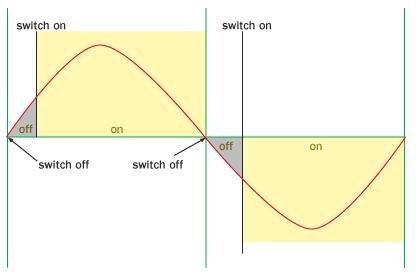
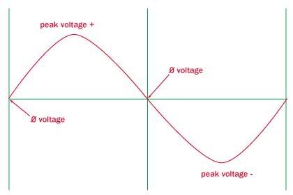
Here's another:

Normal sine wave:
Dimmer1.jpg


Dimmer sine wave:
Dimmer2.jpg
 
Here is a Simple Representation of a Dimmer Pulse,
shown against a AC sine wave.

Never seen one like that where they shorten the peak and the duration from both ends.

Usually they just clip a section of the rising edge like 480sparky shows or for dimming LV lighting via a transformer we would use a more expansive dimmer that clips the falling edge. :smile:
 
Dimmers do not cost much and are easy to install but there is a problem ahead. The political winds are blowing so strongly in favor of compact fluorescent lamps that we may be forced replace incandescent bulbs, that do work with dimmers, with CFL?s that don?t work with dimmers. Fluorescent lights don?t like to be dimmed, even those marketed as dimmable. When you use ?dimmable? fluorescent lamps on a dimmer switch, it actually shortens the life of the lamp. Dimmers just don?t work with most fluorescent lamps even when you have a special ballast.
 
Never seen one like that
where they shorten the peak and the duration from both ends.

Comment is well taken.
It is from a very different application.
I was looking for something that would be simplistic, not accurate.
Thanks for the comment.

The following is not an 'electrical' answer,
but here goes with some words.

A signal like this would come from a Bipolar Active Diode circuit,
when trimmed down below a useful function.
The empty space in the curve is called 'dead space'
and it not usually a useful generation.
Some 'dead space' occurs as the input signal reverses its activity
from positive half-wave to negative half-wave.
Most Active Diode circuits will pass the reverse leakage, as a small blip.
I developed several circuits based around an Op-Amp
with full-wave rectification in the negative feedback loop,
which controlled this phenomena very well.
The best of these circuits allowed full-wave rectification of an AC signal
which was passing microAmps through the diodes, measuring milliVolts.
Electricians usually think of .7 Volts as the forward breakdown voltage of a Diode. Diodes (in the purest form) will function on a log curve down 7 decades, down in the microVolt range.

Anyway, that is all O.T. (Off Topic).
Esoteric stuff, of which my dreams are made.
 
... When you use “dimmable” fluorescent lamps on a dimmer switch,
it actually shortens the life of the lamp ...

David,
Sounds right.
I 'Run' CFLs, I do not 'Burn' CFLs, in case you like a little joke.

As I have thought about it, that being the sort of thing with which I have a talent. So, I looked the function of the switcher supply that powers the CFL, and the start-up requirements of a Flourescent tube. It occured to me that when a CFL is dimmed, it may have to restart, which is a high voltage impulse. This impulse stresses the insulation of the components in the switcher supply, on the load side. This constant, or frequent, restarting may be the reason for the shortened life-usage.

To test this 'thought',
I connected a CFL to diode, set it on, and left it on for 365/24/7,
which is about a year. At the manufactures rated 5 hours per day,
this worked out to 4 years of life-use.
The CFL was still going strong, running on Half-Wave AC.
( I only tested this on a Phillips CFL of the 2002 year model. )

I also set a CFL to on, and turned it on and off at least 10 times per day.
It basically ran all day and night, 365/24/7.
This CFL ran about 3 years of life-usage.
This is within the tolerances spec'ed by the manufacturer.

I also did experiments with CFL's running in a very hot enclosure, 130 degrees F.
They darkened substantially, and expired in a year.
Which indicates that placing them in downward facing shades
may shorten the life-usage.

I admit, these experiments only produce anecdotal data,
but I think it puts me in the right ball-park.

There may well be other major contributing factors,
which have not occurred to me.
This is not Truth, this is just one guy's experience.
So, perhaps I should give the standard
"not liable for any damage" EULA.

Comments are welcome.
I have learned a lot from some of the real electricians / engineers here.
That is what the forum is about.
 
Last edited:
Never seen one like that where they shorten the peak and the duration from both ends.

Usually they just clip a section of the rising edge like 480sparky shows or for dimming LV lighting via a transformer we would use a more expansive dimmer that clips the falling edge. :smile:

I believe even the cheapies use a TRIAC which works on the rising and falling edges of the wave.

It should be noted though that dimming an incandescent lowers its efficiency.
 
I believe even the cheapies use a TRIAC which works on the rising and falling edges of the wave.


That is different then all I have read. I have read the cheapies clip the rise and the resulting sudden spike raises heck with transformers so we have to use one that clips the fall.
 
...I also did experiments with CFL's running in a very hot enclosure, 130 degrees F.
They darkened substantially, and expired in a year.
Which indicates that placing them in downward facing shades
may shorten the life-usage....

I have some customers who have been experiencing premature failures of CFL's in downlights. So bad that they are replacing them at about the same rate as the old incandescent or halogen bulbs used previously. :mad:

These were the R-30 shaped ones specifically designed for use in lighting fixtures, downlights, etc.
 
090228-1403 EST

An SCR or Triac is device that has a high impedance state until triggered. Once triggered it is in a low impedance state until the current drops below a holding current value.

In a dimming application with a resistive load the device is triggered at some point in a half cycle relative to most likely the voltage zero crossing. This might be a 90 phase shift. Because it is a resistive load current will flow until the next current zero crossing and that is also a voltage zero crossing.

The turn-on point may not be exactly the same angle for both the positive and negative half waves. If not equal, then a DC component is created. No real problem for a filament lamp. However, in the case of a transformer a DC component will unbalance the hysteresis curve and increase the magnetizing current. Not the worst problem. A chopped sine wave has a lot of harmonic content and this is probably a greater problem.

To start and stop excitation within a half sine wave requires something more than just an SCR or Triac, or a different device like a power FET. A start and stop excitation within a half cycle will not eliminate harmonic content but just change it. Nor is this start stop technique a solution to the DC component problem.

ON dimming CFLs.

I found that a standard CFL has a fairly constant light output with a considerable variation in the input from a phase shift dimmer. Assuming that diode is charging a capacitor then this makes some sense. On the other hand dimming with a Varic produced a somewhat useable dimming capability. This again makes sense because now the peak input voltage is being reduced. Dropout occurs about 45 to 50 V. This says nothing about expected life of the lamp under these conditions.

A so called dimmable CFL is slightly dimmable with with a phase shift dimmer. But nothing close to the minimum light I can get with a standard CLF and a Variac. The dimmable CFL is almost constant light output with varying voltage from the Variac. Dropout is about 95 V.

.
 
That is different then all I have read. I have read the cheapies clip the rise and the resulting sudden spike raises heck with transformers so we have to use one that clips the fall.

The key is that "rise" can be a negative or positive rise. If they clipped only one edge, we could only dim to half power.
 
090228-1442 EST

rattus:

I had the interpretation that rise was the 0 to 90 side of the half wave, and fall was the 90 to 180 deg side of the same half wave.

Are there any dimmers using a single SCR and only modulating the on time of every other half cycle? This would mean there always was one full half cycle, call it the negative half, and the other, the positive half was phase modulated. I doubt such exists.

A half wave rectifier in series with an incandescent lamp does not provide much dimming.

.
 
These were the R-30 shaped ones specifically designed for use in lighting fixtures, downlights, etc.

KB,
That reminds me of the ones I pulled down which had been in an enclosed fixture, and the tubes were markedly dull gray in color, not white.
I am thinking that the heat of the fixture was causing early deterioration.

Does that fit your scenario?
 
090228-1442 EST

rattus:

I had the interpretation that rise was the 0 to 90 side of the half wave, and fall was the 90 to 180 deg side of the same half wave.

Are there any dimmers using a single SCR and only modulating the on time of every other half cycle? This would mean there always was one full half cycle, call it the negative half, and the other, the positive half was phase modulated. I doubt such exists.

A half wave rectifier in series with an incandescent lamp does not provide much dimming.

.

That is my understanding also about the rising and falling edges of a sinusoid.

It is more instructive to say that a portion of each lobe is switched off beginning at the zero crossing just as the diagram indicates. iIn theory, the OFF time can vary from zero to 180 degrees--full ON to full OFF.

I don't think any dimmers use SCRs. Like you say, they wouldn't work very well.
 
Status
Not open for further replies.
Top