stupid Q. does light on dimmer use less electricity?

Status
Not open for further replies.
Not sure that's entirely correct......
For simple numbers take, for example, a 120V, 120W lamp being fed by a solid state dimmer. Nominal current is !A.
Fully phased on, the dimmer might drop a couple of volts, thus, in round figures, dissipates 2W. The lamp now has 118V across it. If its temperature didn't change, it would now consume about 116W.

Of course it isn't as simple as that. The temperature will change some which makes it not such a simple calculation. The power may not go down very much but I think it unlikely to go up.

P.S.
I apologise for having spelt your name incorrectly in an earlier post.
At least I remembered who the BASF guy was. :wink:

I would have been more accruate if I stated that the light efficacy would be affected, eg. with the dimmer you would not get the same lumen/watt ratio, but always less weather it is at full or at partial load.

No problem, at my previous location - also with BASF - I had a collection of the mis-spellings. I had about 50, none the same.:smile:
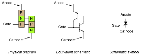
 
you dim the light and a pot drops part of the load of the bulb. less voltage in the lamp, less wattage. the circuit is still 120v so it's still dropping 120V. if the R of lamp is 10 ohm, 120V = 12A so lets say it's 100 ohms for 1.2A. add a 100 ohm pot in the switch, now its 120V/200ohms=.6A half of the 1.2, duh. if P for the ckt is E x I 120V x 1.2A = 144W; 120V x .6A with dimmer = 72W, half the wattage. so savings of half to have the lamp on dim.

P for each load adds up to Ptotal. for dimmer switch you have 60V x .6A = 36 W and lamp is same,since i said R was the same, so 72W total for ckt with dimmer and lamp. gee just did that...

i don't know, i guess thats as it should be, but it seems to me that even with a dim light, those dimmers have big heat sinks, and can get hot, so they are using alot of the energy that i should be saving by having the light dim instead of bright.

i am no engineer, i don't really need all this math crap beyond ohms law, can somebody tell me if i would really be saving half the power if i have my light on half as bright? should i actually even care? regardless, i appreciate your time. seems like i am missing something but maybe i'm not. probably should be trying to think about something else.

What the deal is is a reostat is (see all the is's :grin:) a series resister. A triac driven dimmer chops off a portion of the AC wave. Simply use Ohm's for a series resistance to calculate the wasted energy, in the form of heat, for a reostat.
 
Well. I spent about 10 minutes writing a response but I appearantly pushed the wrong button accidently and the whole thing went away. One stupid button. I can't even imagine which one might do such a thing. It's never happened before, but it has just now.
May I suggest typing longer resonses in Notepad, and copy'n'pasting it into the forum window when you're done?

I guess it doesn't that much matter how to sort out the difference between a reostat and a triac controled dimmer. Cause I'm sure not gonna do it again tonight.
Okay, here's a simple one:

A 600w variable resistor would probably be as big around as a coffee can, and put out considerable heat while dimming.

A 600w dimmer uses a special type of transistor that varies the percentage of each half-cycle it passes to the load.

What the . . . . button would do such a thing.
Maybe the 'back' button, or the 'enter' key. Any key would do it if your text was highlighted. Did you try 'Control-Z'?
 
I have removed 5 keys from my keyboard because they are a problem. These are caps lock, the two keys on the right adjacent to control, one of these is alt, and the two keys to the right of the space bar.
No, I guess you didn't. :D
 
A 600w variable resistor would probably be as big around as a coffee can, and put out considerable heat while dimming.

It could be but doesn't have to.

A 600w dimmer uses a special type of transistor

It's actually a special kind of diode called an SCR. It's a diode with a gate that controls whether it conducts. A dimmer uses something called a TRIAC. It's two SCRs paralleled in opposite directions, that makes a device that works on the entire AC wave.
 
It's actually a special kind of diode called an SCR. It's a diode with a gate that controls whether it conducts. A dimmer uses something called a TRIAC. It's two SCRs paralleled in opposite directions, that makes a device that works on the entire AC wave.
Added: (I used the term "transistor" for non-technical-minded customers.)

Yes, and instead of having cathodes (K) and anodes (A), they have main terminal 1 and 2 (MT1 and MT2). They, too, have trigger (T) terminals. I've seen schematics with a bi-directional diode called a DIAC in line between the timing circuitry and the T terminal.

They both must be re-triggered each half-cycle because SCR's and TRIAC's stop conducting when the AC waveform reaches 0v at the crossover. Dimmers take advantage of this and only have to delay the trigger during each half-cycle; the cutoff is automatic.

A dimmer that actually altered the voltage instead of reducing the duty cycle, such as a VARIAC (variable auto-transformer) would be easier on lighting, especially non-incandescent types. Stage lighting used to use racks of VARIAC's with linkable handles.

In fact, you can get motor-operated VARIAC's for remote control where a VARIAC is the dimmer/controller of choice.
 
Last edited:
090304-1501 EST

Larry:

The SCR or Triac turns off when the current drops below the holding current. In the case of a resistive load this is also the voltage zero crossing.

TRIACs may have a problem with turn off with inductive loads. Back-to-back SCRs do not have this problem.

.
 
TRIACs may have a problem with turn off with inductive loads.

No question there. That's why extra stuff has to be done to the output section for inductive load handling. There problem isn't so much turning off as blowing up.

TRIACs may have a problem with turn off with inductive loads. Back-to-back SCRs do not have this problem.

TRIACs are back to back SCRs, at least if I'm not misunderstanding what's meant by back to back.

I wouldn't recommend using a variac on flourescent lighting Larry, as much as I do like those things.
 
03206.png


I guess I can't argue that it can be sort a two transistors. Keep in mind that schematic is an "equivelent schematic" meant for simplification.
 
Last edited:
090304-1613 EST

physis:

A back-to-back pair of SCRs are two individual SCRs. The anode of one is connected to the cathode of the other, and vice versa. In this case one SCR is completely turned off while the other is on. This allows time for complete turn off of the one being turned off.

See my earlier reference, post #25, to Bill Gutzwiller and his oral comments. I believe this was discussed in the oral on the Triac.

.
 
0155.GIF


This is what it used to look like. The gate junction between the two N's, once energized, causes J2 and J3 to remain conductive. In effect, making the device essentially a PN device while engaged.
 
I didn't mean to trigger :)wink:) such a discussion. I just use the term 'transistor' when explaining dimmers to customers. If I said "they use a special type of SCR (or Thyristor," they wouldn't know what the heck I was talking about. Everyone knows the word 'transistor.'
 
090304-1636 EST

I have added some photos to my web site with plots of CFL power input and intensity, and comparison with incandescent. See photos P10 thru p18 at
http://www.beta-a2.com/EE-photos.html .
If you are on dialup this may take a long time to load.

All the photos are 640 wide and will easily print out using Internet Explorer.

The results are quite interesting. With quantitative data one gets a much better understanding on how to apply these devices.

.
 
Nobody outside of engineering circles even have any tolerance for the excessive depth I get into sometimes, I would certainly never lay this stuff on a customer, even an employer. Outside of this place, I usually pretend I'm stupid, Yeah, right. :grin::grin:
 
03206.png


I guess I can't argue that it can be sorta two transistors. Keep in mind that schematic is an "equivalent schematic" meant for simplification.

No, it is not two discrete transistors, but if you have an NPN or PNP sandwich, you have a transistor. Here we have two such transistors all mushed together. Sort of an integrated circuit.

What you see in the equivalent is what you get.

Once the device is triggered, the positive feedback overwhelms the base (gate) current, then the gate has no effect.
 
Status
Not open for further replies.
Top