SWER vs Single Primary

Status
Not open for further replies.

Open Neutral

Senior Member
Location
Inside the Beltway
Occupation
Engineer
A friend is a non-technical employee of a PoCo.

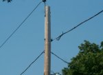
He's insisting that the pictured distribution is SWER where as I say the visible MGN is the primary return.

My question is: is there any domestic SWER left in the lower 48? I know the original REA co-ops used it. and it was seen more recently in Alaska.
 

Attachments

  • SinglePrimary.jpg
    SinglePrimary.jpg
    52.5 KB · Views: 2
I can assure you there is primary current flowing on all those secondary neutral conductors as well as the messenger for the phone or cable TV farther below. Does this distribution system ever get to a point where there is only just the "hot" primary conductor and nothing else between poles?
 
I can assure you there is primary current flowing on all those secondary neutral conductors as well as the messenger for the phone or cable TV farther below. Does this distribution system ever get to a point where there is only just the "hot" primary conductor and nothing else between poles?

Without seeing more, it is possible the pic is of an SWER. If the top conductor was the MGN, why the large insulator?

Here are some pics of other SWER systems. Note the similarities.

View attachment 8433View attachment 8434

The Wiki article mentions USA systems, but not where except for the latest Alaskan run. It also mentions that SWER systems are used in rural areas for irrigation and lighting. That may be what your pic is of. But without seeing more, like what is on the other poles, it's tough to say for sure.
Most of time MGN and secondary neutral are same conductor and not separate conductors.

If using SWER for primary AND you also have secondary conductors on same poles, the secondary neutrals are going to have less resistance than the earth and will carry primary neutral current, the only way around this is to not ground the secondary but that is not going to happen with grounded systems. If you leave a subdivision, or other area and have no secondary conductors then you will go back to seeing only ungrounded conductor(s) for primary conductors on the poles.

Your picture on the left can not be verified from the picture alone if it is true SWER or not. The top line of the secondary lines is usually the grounded line, but is also bonded to the primary grounded conductor terminal or case of the transformer - effectively making it parallel to the SWER if it is a SWER, and chances are more primary current is flowing in that conductor than in earth at that point of the primary circuit.

If you were to go to an isolated area of this distribution system and find only the primary phase conductor and no neutral conductor run between poles, then you will know it is SWER at that point of the system, what goes out on one conductor has to come back on something to be able to have current.
 
Trying for a more detailed picture

View attachment 8440

Zooming in makes no difference, the primary and secondary neutral conductors of that transformer are going to be bonded together which means that even though the neutral conductor that is present may be intended for the secondary, it will have primary current imposed on it just because both primary and secondary are both grounded and are both connected to each other at just about any point they come near each other in the distribution system.

If that neutral conductor would run a couple spans and connect to another transformer then there is effectively no SWER between those two transformers even if the main supply to the area or isolated sections of the area is SWER.
 
Err, the top is the sole primary. The MGM below has a bracket but I see no insulator....

If you are talking about the OP's pic, all I see is the primary 'hot' at the top and a group of secondaries below. The lowest cable is communications cable.

Look at this schematic

View attachment 8445

What is on the pole is consistent with a pole carrying the conductors on the far right side of the schematic. One primary hot (no primary ground, that's at the transformer, not pictured) and a set of grounded secondaries.

That doesn't prove that we are looking at an SWER, but it is indeed a distinct possibility.
 
Perhaps we have a definition issue, but to me, it's SWER IFF there's one primary on the pole, period. Or another way to put it is: there is no MGN back to the substation; all the return current is via Mother Earth.

I've seen it in the Outback but in any place with buried utilities, I'd be surprised to find MGN-less distribution. The cathodic protection issues would be debilitating.

Related to this in a peripheral way are the ground arrays on the Pacific Intertie. It runs bipolar (i.e. 2 wires) but I guess those massive grounds are needed during a fault.
 
Looks to me like the primary is on top, and the secondary wire ACSR conductor is also the main line neutral. It appears that there is one house fed from one side of the pole and that secondary wire is going to a transformer. The two tails that are taped back are fed from another transformer probably a couple of spans down. Lots of neighborhoods are wired this way.
 
Perhaps we have a definition issue, but to me, it's SWER IFF there's one primary on the pole, period. Or another way to put it is: there is no MGN back to the substation; all the return current is via Mother Earth.

I've seen it in the Outback but in any place with buried utilities, I'd be surprised to find MGN-less distribution. The cathodic protection issues would be debilitating.

Related to this in a peripheral way are the ground arrays on the Pacific Intertie. It runs bipolar (i.e. 2 wires) but I guess those massive grounds are needed during a fault.

But primary and secondary neutrals are often (almost always) the same conductor, there is no point in running separate conductors as they are both going to be bonded together at every pole anyway if they were separate conductors. None of the pictures in this thread are clearly SWER installations as there is grounded conductors in the photos but we can not tell if they are isolated from the primary in any way or not.
 
When I was living out in the Everglades we had a SWER system that fed a small local network out there, the main incoming 19.8kv primary from the west coast went to a large transformer that had 2 bushings, one of the bushing went to a very large grounding electrode system that was fenced in because there could always be a difference of voltage potential between it and earth, the secondary of this transformer was kept isolated from the primary grounding and had its own grounding electrode system, the secondary system was a 4100 volt system and had a MGN ran to each pole and hit a pole electrode every so many poles, the service transformer at each house from the 4100 volt primary was a one bushing transformer and it's secondary neutral was bonded to the MGN, I remember the warnings on the fence that surrounded the SWER transformer and the electrode system warned of high voltage are present inside of the fence, the fence in area was way bigger then the area of the transformer and its electrode system, I can remember if the ground voltage detection system detected a voltage higher then 30 volts from the grounding electrode system on the SWER side it would shut the system down, we would be without power for days until they came out and installed a new grounding electrode system, after they built the JetPort which was to become a new international airport for Miami as well as for the south west coast, they did build the jetport but it became just a pilot training center, they had to bring out 138kv lines to feed a substation for the new jetport, when they did this they did away with the SWER system and we got a MGN system.

So after seeing how large the electrode system was for this SWER system I would be very doubtfully that those photos are of a SWER and the fact that the area around the SWER electrode system would have to be rendered unaccessible by a fence or other means, also all SWER systems do not bond across the transformer they are kept isolated other wise you would have a ground to earth voltage present in the whole system generally the SWER system would hit a transformer then changed over to a MGN system that fed the local service transformers.

The SWER system we had, the electrodes were replaced at about every two to 3 years as they would dissolve from the current reaction flowing to earth, Lee County COOP would come out and install the new electrodes within a couple days of when the earth voltage detectors would shut the system down, every time we would be without power for a few days, which was quit common from just storms or Everglade fires so we all either had generators or refrigerators that ran off propane and many lanterns it was just a norm for us to not have power.
 
If you are talking about the OP's pic, all I see is the primary 'hot' at the top and a group of secondaries below. The lowest cable is communications cable.

Look at this schematic

View attachment 8445

What is on the pole is consistent with a pole carrying the conductors on the far right side of the schematic. One primary hot (no primary ground, that's at the transformer, not pictured) and a set of grounded secondaries.

That doesn't prove that we are looking at an SWER, but it is indeed a distinct possibility.

The attached diagram you posted has a problem, while most SWER systems I have read about and the one we had in the Glades would have a two bushing transformer on the primary it is possible and makes more sense that the can be bonded to the primary grounding as it is more likely to fault to the can from the bushing from animals or birds,
the secondary center tap in the diagram is shown bonded to the can instead of the primary as it also shows the arrestor is bonded to the can from the primary circuit, this would put the primary voltage onto the secondary center tap which would be a very big problem in a SWER system, in most of the SWER systems where the first isolation transformer is the earth return point, the secondary is kept isolated to the next pole then at this pole they install the electrode system for the MGN of the secondary system at least where they feed a small distribution system like the one we had.
 
Status
Not open for further replies.
Top