Anode
Member
- Location
- Washington, USA
We have a project where we are planning on future expansion in our run to the point of interconnect. Despite the system size only being 10kWdc, we are putting in infrastructure that will accommodate maximum utilization of the roof, for future system expansion.
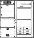
Our intent was to tap feeder conductors in switchboard with insulated piercing connectors to each phase. We had not confirmed what was inside the switchboard. Today we removed the cover off the customer side of the switchboard, which is on the right side, and saw busing fed from the left (utility) side. On the lower third portion of the customer side, there are the breakers for distribution. My question is, since there is no main circuit breaker in the switchboard, are we still bound to 120% of the bus bar rating above the distribution breakers? Or can we tap the bus above all those breakers and circumvent being held to 20% of 600A rated busing?
Picture of the diagram of the switchboard, and a crude rendition of what the busing looks like on the customer side.


Side note: MFG is fine with taping the busing on the customer side, and entering the switchboard on the customer side.
Your help is greatly appreciated.
Our intent was to tap feeder conductors in switchboard with insulated piercing connectors to each phase. We had not confirmed what was inside the switchboard. Today we removed the cover off the customer side of the switchboard, which is on the right side, and saw busing fed from the left (utility) side. On the lower third portion of the customer side, there are the breakers for distribution. My question is, since there is no main circuit breaker in the switchboard, are we still bound to 120% of the bus bar rating above the distribution breakers? Or can we tap the bus above all those breakers and circumvent being held to 20% of 600A rated busing?
Picture of the diagram of the switchboard, and a crude rendition of what the busing looks like on the customer side.
Side note: MFG is fine with taping the busing on the customer side, and entering the switchboard on the customer side.
Your help is greatly appreciated.