symbols on electrical drawings

Status
Not open for further replies.

wlancaster

Member
Location
greenville, sc
Occupation
Building Inspector
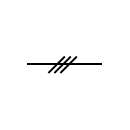
I recently took a test that asked how many conductors are in a conduit with no hash marks with a sample drawing illustration...best I can figure a straight line denotes control wiring or maybe an empty conduit? I can't remember all the answers available but I believe all the choices were numbers and there could have been a 0 as one of the options. Any ideas on what just a straight line indicates? I know the question is a little vague and symbols may vary somewhat depending on the engineer doing the drawings. I'm an inspector with not a lot of practical or hands-on experience in the electrical trade and appreciate the help. The symbols for the other conduits (ones with conductors) looked something like what I found on line, see below:
Line with three conductors symbol
Line with three wire
thanks for the response, good point, I could have missed the legend because you navigate the drawing with a magnifying glass which is not ideal
 
FWIW

What is the British standard for electrical symbols?


IEC60617 is the requirement for symbols for diagrams of electrical installations in the UK now, and therefore any deviation that leads to injury or death as a result of non-conformant diagrams may indicate contributory factors on the part of the organisation responsible for the diagrams 7 Jul 2010

I had a draughtsman who was guy good at that.
 
I recently took a test that asked how many conductors are in a conduit with no hash marks with a sample drawing illustration...best I can figure a straight line denotes control wiring or maybe an empty conduit? I can't remember all the answers available but I believe all the choices were numbers and there could have been a 0 as one of the options. Any ideas on what just a straight line indicates? I know the question is a little vague and symbols may vary somewhat depending on the engineer doing the drawings. I'm an inspector with not a lot of practical or hands-on experience in the electrical trade and appreciate the help. The symbols for the other conduits (ones with conductors) looked something like what I found on line, see below:
Line with three conductors symbol
Line with three wire

In my line of work that’s a Vee Phase line.
 
I took a test with almost the same questions, the right answer for the question should be 3 for how many straight conductors are, however the meaning for the lines depends of the type of electrical drawing and the installation that they shows (power plant, lighting plant, control ladder diagram, etc)
 
See attached legend from my former consulting days. I believe this to be industry standard throughout that most engineers or electricians would easily recognize. We used these hash marks for voltages lower than 480V. Typically, single phase loads like 277V, 240V, 208V and 120V. Usually used these on the receptacle and lighting drawings. That being said, obviously a custom legend could differ....but most would agree with the attached nomenclature.

The 480V loads where typically spelled out in this type of fashion for example: 3#8 +1#10 Gnd. No hash marks for the big power load stuff.
 

Attachments

  • symbol legends.pdf
    150.2 KB · Views: 46
See attached legend from my former consulting days. I believe this to be industry standard throughout that most engineers or electricians would easily recognize. We used these hash marks for voltages lower than 480V. Typically, single phase loads like 277V, 240V, 208V and 120V. Usually used these on the receptacle and lighting drawings. That being said, obviously a custom legend could differ....but most would agree with the attached nomenclature.

The 480V loads where typically spelled out in this type of fashion for example: 3#8 +1#10 Gnd. No hash marks for the big power load stuff.
as long as there is a legend I don't really care what symbols are used.
 
Three slaches represents 3 hot wires. A longer slash becide the 3 shorter slashes represents the neutral. A ground wire is a short slash withe the letter G. This is typical for a 3phase, 4 wire home run complete wit the equipment ground. The neutral is common to the 3 hot wire circuits. The arrow head represents the home run and direction to the supply panel. The circuit numbers ate typically included at the arrow head ( 1, 3, 5 )
or ( 2 , 4 , 6 )
 
Status
Not open for further replies.
Top