The AC Inverter Circuit I made

Status
Not open for further replies.

ling1995

Member
Location
beijing,china
Urgent help !
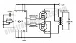
I have made a DC to AC Inverter Which provide s 220V AC when when a 12VDC power source is provided. It can be used to power very light loads like night lamps and cordless telephones, but can be modified into a powerful inverter by adding more MOSFETs. It uses 2 power MOSFETs--IRFZ44E (this is the IRFZ44E PDF , it's different form the schematic diagram. ) for driving the output power and the IC--4047 as an astable multivibrator operating at a frequency of around 50 Hz. The output transformer has a 9V-0-9V, 2 Amps on the secondary and 230V on the primary. Aren't MOSFETs suitable here?

After that I tested circuit on bread board,however there was some humming noise as well a lot of heating due to which bread board started melting. Also a sound of beep was their. Why it is so ? Can anyone here guided me?
 

Attachments

  • 6.1.3.jpg
    6.1.3.jpg
    53.6 KB · Views: 0
....humming noise as well a lot of heating....

1. Huge turn on and turn off FET losses due to the 100 ohm gate resistor, probably should be 5 or 10 ohms, plus number 2.

2. 'sounds' like your transformer is saturating (pun intended) or core is loose. Surprised your FETs are not destroyed.

3. ....astable multivibrator operating at a frequency of around 50 Hz....
50 Hz?? more powerfull - nope, not at 50 Hz

You need to use a more complicated control circuit, such as PWM driver at 100 kHz for higher power at high efficiency. Do a web search for inverter design.
 
170601-0803 EDT

junkhound:

On the surface I see nothing wrong with the basic circuit concept. I have not looked into the details of the components.

A gate resistor of 100 ohms vs 50 ohms is of no consequence at this frequency, nor is gate heating from a good square wave. We have to assume the CMOS oscillator is producing a good square wave.

We know virtually nothing about the transformer, but there could be core saturation which is a function of frequency and voltage. In 1955 I built such an inverter that self oscillated using a square loop core and Delco germanium power transistors with about a 100 W capability. By using a square loop material core saturation was used as part of the oscillator function.

ling1995, The center tapped low voltage winding should be called the primary because that is the incoming side.

Loose laminations or square wave drive of the transformer can be the source of noise if the core is not being saturated much. ling1995, you could try increasing the frequency to 100 or 150 Hz and see if there is a gross difference in noise. This changes the volt-time integral and the maximum flux density level.

.
 
170601-1049 EDT

ling1995:

You are probably substantially overdriving the transformer.

The integral of a function is the area under the curve between set limits.

The peak voltage of a 9 V sine wave is 12.7 V.

Consider a half sine wave of base width 1. Since the average value of a half sine wave is 0.636 of its peak, then the area under this curve is 0.636*12.7 = 8.08 . The area under a square pulse of 12 by 1 = 12. Thus, you are overdriving this core by 12/8.08 = 1.49 . That is probably causing large magnetizing current spikes near the end of each square pulse. If you have a scope look at the current to the primary center tap with no secondary load. You should see sharp spikes. This occurs at the voltage zero crossings.

.
 
Status
Not open for further replies.
Top