mbrooke
Batteries Included
- Location
- United States
- Occupation
- Technician
...Actually what are they even trying to accomplish? :blink:
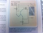
It seems to me that they should have taken the wye point of the zig-zag as the synthesized neutral.
It seems to me that they should have taken the wye point of the zig-zag as the synthesized neutral.
The CT's are confusing
seems they are there to mitigate an imbalance
but the end result is a 277 load with a neutral
which could introduce the imbalance.....?
~RJ~
While I'm not smart enough to proofread how they did it, it says they are using it to derive a neutral from a source that doesn't have it. I can see the need.

Yup- thats the goal. In this case they have corner ground
Where and when is the pic from?
Looks like it was discussed here several years ago. The 1999 Handbook shows it connected in the center. See Post #11: http://forums.mikeholt.com/showthread.php?t=138570
Post #16 seems to confirm it was accidentally changed after that.
Where and when is the pic from?
Looks like it was discussed here several years ago. The 1999 Handbook shows it connected in the center. See Post #11: http://forums.mikeholt.com/showthread.php?t=138570
Post #16 seems to confirm it was accidentally changed after that.
I think Google might have dug it up from this forum- or it was taken from the IET forums assuming it was there first. looks like the ct's provide gnd fault protection
it looks like if ct2 + ct3 NE ct1 then shunt trip
That would be it- thanks
Agreed, you can find a more technical explanation (if you're so inclined and have a copy) in chapter 1 of the IEEE Std 142 "Green Book" under zigzag transformers.