Top App contest - Buck/boost question

Status
Not open for further replies.
Smart $ said:
Diagram SP-6 is not limited to 216 to 240. Look at the second page for type Y xfmrs, at the bottom of of the 208 to 240 column.

That is the thing about buck-boost transformers... the output voltage will vary with the loading of it. No load condition was set in the OP problem. While Jim Dungar is basically correct in his post above regarding the physics of it, I disagree with his comment about manufacturer's literature, because loading must be take into account for a specific output voltage.

All transformers are chosen based on their nominal open circuit voltage be they 7200-120/240, 480-208Y/120 or 120-24V units.

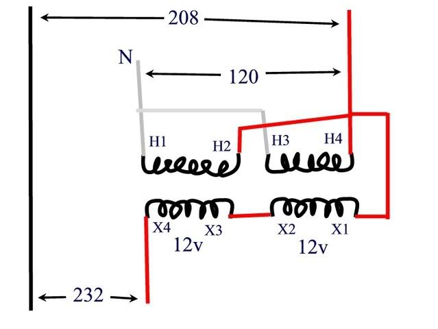
The nominal voltage changes available with a 120/240-12/24 transformer connected in buck-boost using standard additive connections are: 5%, 10%, and 20%. For a 120/240-16/32 they are 6.6%, 13.3% and 26.6%. The formulas for determining the voltages are: HV = LV*(1+%) and LV = HV/(1+%). It does not matter whose transformers they are. It does not matter if the transformer bank is 1-phase, 3-phase open delta, or 3-phase wye.

How close you get to any specific output L-L voltage depends on how many digits you use in your calculations, and what number you start with. Remember there is no such thing as an actual 208Y/120, it is actually 207.8Y/120.
 
jim dungar said:
The formulas for determining the voltages are: HV = LV*(1+%) and LV = HV/(1+%).

There is an entire other set of connections which give:
LV = HV * (1-%) and HV = LV/(1-%)

This is simply swapping line and load, eg. using what is commonly a buck connection with line and load reversed to provide a boost.

-Jon
 
winnie said:
There is an entire other set of connections which give:
LV = HV * (1-%) and HV = LV/(1-%)

This is simply swapping line and load, eg. using what is commonly a buck connection with line and load reversed to provide a boost.

-Jon

It does not make a difference whether you are bucking or boosting the formulas will be the same.

What changes is your base voltage. I should have included that LV is my base, therefore %change = (HV-LV)/LV. You chose HV as the base, so the missing formula is %=(HV-LV)/HV.

And yes, it does make sense to use HV as the base when bucking and LV when boosting. But, this does not change the overall possible %changes of 5, 6.6, 10, 13.3, 20, and 26.6%.
 
Sorry that I was not clear. I also misread your post. You specifically said 'with standard additive connections'; and I was specifically talking about the subtractive connection.

I'm pretty sure that the additive connection is to be preferred because it results in higher efficiency and KVA capability. But I think that the intent of the original question was to get people to consider the subtractive connection.

The 'higher voltage' coils and the 'lower voltage' coils can be connected to add or subtract, and _either_ side can be input or output.

Thus with a 240-24 transformer, with only 10%, (just to simplify the list) you can get the following:
A) HV = LV * 110%
B) HV = LV * 111.1%
C) LV = HV * 90%
D) LV = HV * 90.9%

The equations that you supplied only describe A and D. The original question is answered with B.

-Jon
 
crossman said:
Here is the answer from the contest. I have an issue with it. They are using the 120 volt phase to neutral to put 120 on the BB xfmr, giving 12 v at each secondary. Series this gives a 24 volt boost. Then they take that to the other phase conductor and 208 + 24 = 232.

bb.jpg


Problem to me is that the 24 volt boost is not in phase with the 208 volt, so they do not add up, they must be added vectorially. And this comes out to less than 230 volts.

Well... so does anyone think this works, or am I correct that the 24v is out of phase with the 208 and doesn't add up algabraically?
 
crossman said:
Well... so does anyone think this works, or am I correct that the 24v is out of phase with the 208 and doesn't add up algabraically?

That approach was the first one that I tried, and I discarded it because it didn't work.

As you note, the 24V boost is not in phase with the 208V, and so you need to do vector addition.

If you think about it, you would now have 144V and 120V 120degrees apart. I get 228.9V

-Jon
 
Thank you for confirming my thoughts, Jon. And also thank you for the enlightenment concerning the other BB xfmr connections which I had never considered, i.e. the 111.1% and the 90.9% connections.

Again I learn something from you guys. Good stuff!
 
You can get 233.5 volts from line A to 24 volt boosted line B connecting zig zag. Try the vector analysis. I can't beleve that this problem was on an electrician apprentice test.
 
donaldsullivan said:
You can get 233.5 volts from line A to 24 volt boosted line B connecting zig zag. Try the vector analysis. I can't beleve that this problem was on an electrician apprentice test.

How do you get a zig-zag connection with a _single_ core transformer?

-Jon
 
Primary connected N-A phase and secondary connected B phase, creating B'. This creates a voltage of 233.5 volts from A-B' with a phase angle of 150 degrees. N-A phase is 120 volts, and N-B' is 121.8 volts. N-B has a phase angle with N-B' of 30 degrees. You know zig-zag.

By the way the connection that crossman is showing is not correct.
 
Last edited:
donaldsullivan said:
Primary connected N-A phase and secondary connected B phase, creating B'. This creates a voltage of 233.5 volts from A-B' with a phase angle of 150 degrees. N-A phase is 120 volts, and N-B' is 121.8 volts. N-B has a phase angle with N-B' of 30 degrees. You know zig-zag.

I'm sorry, I've tried to figure this one out graphically. Your description of the A-B' voltage and the N-B' voltage implies a B-B' voltage of 62.4V at 223.4 degrees or 171.2V at 254.6 degrees (there are two possibilities).

You have a single core transformer, so the output phase angle must equal the input phase angle. I don't see how you can get the B-B' voltages that you describe given the supplied transformer.

-Jon
 
I stand corrected. I made a mistake, isn?t the first, and won?t be my last. It can?t be done. The highest voltage is 228.8. I eat my words. Believe me, I?ll be more careful next time.
 
donaldsullivan said:
By the way the connection that crossman is showing is not correct.

Yes, that was the entire point of this thread. The diagram I drew was the given "answer" to the problem. My contention was that it is wrong and indicated such in the post with the diagram. Thank you for confirming that it is not the correct answer.

Also, this question was from a contest between the outstanding apprentices from a five-state area. It wasn't from a test for "average" apprentices.
 
LarryFine said:
Did you ever ask them about my solution in post #2?

When I presented your solution to "those in the know", they informed me that I had misrepresented the question. The output voltage is required to be between 230 volts and 235 volts. Sorry, my mistake. But I really do like your solution.

I had posted the above earlier. I am guessing that you missed my correction.

But as for my original parameters, your solution is P E R F E C T :)
 
Status
Not open for further replies.
Top