hhsting
Senior Member
- Location
- Glen bunie, md, us
- Occupation
- Junior plan reviewer
THE DRAWING DOES NOT SHOW ONE AT THE TRANSFORMER.
Are you just assuming there's a factory installed jumper in the transformer? If that's your concern then ask the person who submitted the drawing about it. Maybe they know something about their transformer that you don't.
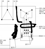
Attached this post: See the red line that has arrow point that has G.
Also see the red line that has arrow point N.
N is neutral and G is equipment grounding conductor primary.
You see that G is bonded to xfmr case. You see that N is bonded to xfmr case.
You see that N is connected to xfmr x0. Follow red line labeled N to see that to center of wye.
You have second N to G bond at xfmr

Sent from my iPhone using Tapatalk