I forgot about my lessons 20 years ago.
How do you compute the impedance of this transformer? It's 500va 230vac to 115vac isolation transformer with this specs:
https://www.hammfg.com/electronics/transformers/line/172.pdf


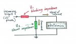
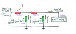
The 500VA step down isolation transformer would be put before the type 3 SPD in the following. I'd like to know the impedance of the transformer and how many length of say AWG 10 it is equivalent to so I can decrease the length of the wire which can be done.

Thank you.
How do you compute the impedance of this transformer? It's 500va 230vac to 115vac isolation transformer with this specs:
https://www.hammfg.com/electronics/transformers/line/172.pdf
The 500VA step down isolation transformer would be put before the type 3 SPD in the following. I'd like to know the impedance of the transformer and how many length of say AWG 10 it is equivalent to so I can decrease the length of the wire which can be done.
Thank you.
")