Here is the exact connection to make it clearer.
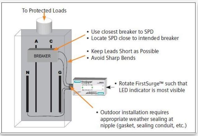
In the main panel is 240v AC power source protected by the 2 pole Siemens First Surge 140,000A SPD type 2.
Then 10 meters away to the load there is this 240-120v step down Hammond 500va isolation transformer:

The 240-120v step down transformer is driving a 120v Leviton SPD type 3 surge protector:

First understand that an SPD works by having significant source impedance so that by divider action, the MOV would have less current and voltage. If one doesn't understand this. Then pls. understand this first because my question is related to this (it's brought up by Golddigger but then he didn't follow with the question what would happen if the impedance at source and equipment is equal hence confusing me for days)..
So what happens when you have say equal impedance in the source and near equipment. What would happen to the SPD type 2 (the Siemens First Surge) at main panel. It's seeing 2 both equal impedance at source and near equipment.
In the main panel is 240v AC power source protected by the 2 pole Siemens First Surge 140,000A SPD type 2.
Then 10 meters away to the load there is this 240-120v step down Hammond 500va isolation transformer:
The 240-120v step down transformer is driving a 120v Leviton SPD type 3 surge protector:
First understand that an SPD works by having significant source impedance so that by divider action, the MOV would have less current and voltage. If one doesn't understand this. Then pls. understand this first because my question is related to this (it's brought up by Golddigger but then he didn't follow with the question what would happen if the impedance at source and equipment is equal hence confusing me for days)..
So what happens when you have say equal impedance in the source and near equipment. What would happen to the SPD type 2 (the Siemens First Surge) at main panel. It's seeing 2 both equal impedance at source and near equipment.

")
