Other than OP'er saying it is required for his situation, I have no idea...Yep. Peanuts for a 1000 kVA transformer. Why bother?
You are using an out of date browser. It may not display this or other websites correctly.
You should upgrade or use an alternative browser.
You should upgrade or use an alternative browser.
Transformer Losses compensation
- Thread starter Sajid khan
- Start date
- Status
- Not open for further replies.
Sajid khan
Senior Member
- Location
- Pakistan
OK. I looked at this for the highlited 1000kVA entry.
The 72.4kVAr would make the PF of the transformer at full load about 0.997.
Do you really want to correct for that?
yes exactly i was looking to compensate for this. But the P.F=0.997 Near to unity, you mean no need for correction.??
Last edited:
Abdel Rahman Mohamed
Member
- Location
- Riyadh,KSA
As per my knowledge it is preferred that we keep away from that unity PF, What about the affect of the capacitive loads we may take the PF to exceed unity So all the motor will inject current, which is not required and has some dangers consequences like i.e insulation damage.yes exactly i was looking to compensate for this. But the P.F=0.997 Near to unity, you mean no need for correction.??
I wouldn't. The normsl customer spec is for load side correction to 0.95. The risk of correcting a PF so near unity is that you may go into leading PF and that can cause the volts to increase.yes exactly i was looking to compensate for this. But the P.F=0.997 Near to unity, you mean no need for correction.??
gadfly56
Senior Member
- Location
- New Jersey
- Occupation
- Professional Engineer, Fire & Life Safety
I wouldn't. The normsl customer spec is for load side correction to 0.95. The risk of correcting a PF so near unity is that you may go into leading PF and that can cause the volts to increase.
This appears to be a case of "close enough is good enough". Do not let the perfect be the enemy of the good.
I wouldn't have put it that way. At the load side, we can make the PF what we want it to be - not just good enough.This appears to be a case of "close enough is good enough". Do not let the perfect be the enemy of the good.
gadfly56
Senior Member
- Location
- New Jersey
- Occupation
- Professional Engineer, Fire & Life Safety
I wouldn't have put it that way. At the load side, we can make the PF what we want it to be - not just good enough.
I was unclear; I meant in this specific instance that there was little to be gained from trying to improve a PF of 0.997 (good) to 1.000 (perfect).
Load PF correction is typically done on the load side of the transformer... and closer to individual load level rather than at the supply for all connected loads. How and where it is handled is somewhat dependent on whether you a continuous or mostly non-continuous operation. If the major loads are operating 24/7/365, you can correct anywhere up line. If you have all start-stop major operations, you want correction for each load. In between is a compromise born from analysis.yes exactly i was looking to compensate for this. But the P.F=0.997 Near to unity, you mean no need for correction.??
This approach prevents or helps to prevent overcorrection mentioned by others.
Correction to unity PF is best avoided.I was unclear; I meant in this specific instance that there was little to be gained from trying to improve a PF of 0.997 (good) to 1.000 (perfect).
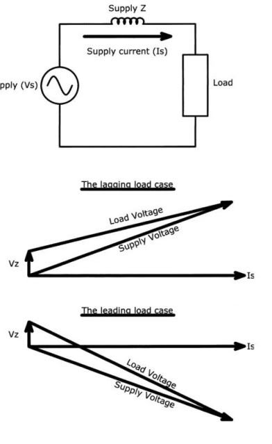
A small change in loading can result in leading PF which can cause a rise in the voltage being supplied.
That's one of the reasons our customers, mostly industrial, specified 0.95.
gadfly56
Senior Member
- Location
- New Jersey
- Occupation
- Professional Engineer, Fire & Life Safety
Correction to unity PF is best avoided.
A small change in loading can result in leading PF which can cause a rise in the voltage being supplied.
That's one of the reasons our customers, mostly industrial, specified 0.95.
Being unafraid to display my ignorance, can you explain how this happens? Not having to deal with it very much, my understanding of PF is a little thin.
You have to draw out the vector diagram.....Being unafraid to display my ignorance, can you explain how this happens? Not having to deal with it very much, my understanding of PF is a little thin.
Sajid khan
Senior Member
- Location
- Pakistan
Load PF correction is typically done on the load side of the transformer... and closer to individual load level rather than at the supply for all connected loads. How and where it is handled is somewhat dependent on whether you a continuous or mostly non-continuous operation. If the major loads are operating 24/7/365, you can correct anywhere up line. If you have all start-stop major operations, you want correction for each load. In between is a compromise born from analysis.
This approach prevents or helps to prevent over-correction mentioned by others.
Smart can you tell from what HP rating of motor it is recommended to put individual compensation? what i know, i read somewhere, is for motor 250HP and above.
Sajid khan
Senior Member
- Location
- Pakistan
Correction to unity PF is best avoided.
A small change in loading can result in leading PF which can cause a rise in the voltage being supplied.
That's one of the reasons our customers, mostly industrial, specified 0.95.
yes all this discussion is very nice, but till now i am not getting the exact what i required.
Let me explain my problem again in other words, for a 3150kVA transformer we required power factor correction capacitor bank in order to improve the power factor of the load connected to the transformer e.g for a 3150kVA transformer we calculate the required capacitor banks size to be 700kVAR. Do i still need to add the KVAR compensation required by transformer for the reactive energy absorbed by transformer alone i.e (700kVAR+0.09x3150kVA= 983.5KVAR). This 0.09 is as per the Schneider guide as attached and mention that it is to be added (see red highlighted box). I didn't do this before in any project but my senior engineer is of the view to add this extra kVAr to size the capacitor bank.
Attachments
Last edited:
No. PFC (power factor correction) is not really my bailiwick. There are other forum patrons better suited to advise you.Smart can you tell from what HP rating of motor it is recommended to put individual compensation? what i know, i read somewhere, is for motor 250HP and above.
electrofelon
Senior Member
- Location
- Cherry Valley NY, Seattle, WA
- Occupation
- Electrician
If I understand you correctly, are you are asking if you should add the compensation that would be required for the transformer with no load, to the compensation that would be required for the motor to get the "total" compensation?
Sajid khan
Senior Member
- Location
- Pakistan
If I understand you correctly, are you are asking if you should add the compensation that would be required for the transformer with no load, to the compensation that would be required for the motor to get the "total" compensation?
Yes this is what i mean.. i.e Transformer alone KVAR requirement+ all other loads
It's the load you need to compensate for. Not the transformer.yes all this discussion is very nice, but till now i am not getting the exact what i required.
Let me explain my problem again in other words, for a 3150kVA transformer we required power factor correction capacitor bank in order to improve the power factor of the load connected to the transformer e.g for a 3150kVA transformer we calculate the required capacitor banks size to be 700kVAR.
Sajid khan
Senior Member
- Location
- Pakistan
Any other has idea, please shareNo. PFC (power factor correction) is not really my bailiwick. There are other forum patrons better suited to advise you.
thanks
Sajid khan
Senior Member
- Location
- Pakistan
ThanxIt's the load you need to compensate for. Not the transformer.
Sent from my GT-I9300I using Tapatalk
- Status
- Not open for further replies.