Transformer Primary Impedance

Status
Not open for further replies.
Re: Transformer Primary Impedance

Originally posted by al hildenbrand:
All the field that is not in the core is small enough, that, for purposes of trying to understand the basic notion, it is simply ignored.
Wait isn't that the magnetic field under the high voltage towers in our back yards that cause cancer? :eek:
 
Re: Transformer Primary Impedance

I really enjoy it here. Seriously!........
Every once in a while, god tricks me and I get to feeling half way intelligent,,,,only to come here and eat humble pie.....reading posts from charlieb and a few others have made me get used to the taste.
Now if I could only retain what I learn.
 
Re: Transformer Primary Impedance

For my understanding, the notch to take it down to is the simple line (theoretical line) of current coming from the left and going to the right. A concentric magnetic field surrounds the current.

As the current goes to zero, the field reduces to zero. The field "collapses" into the line of current one "magnetic line" at a time.

This, by itself, is a relative motion. The field reducing in strength around the line of current will generate current.

Understanding this as a building block allows adding the next building block which is a second line (theoretical), close by, that is capable of carrying current.
 
Re: Transformer Primary Impedance

Hello Sam

I had just assumed that if you had your electron Microscope out of the shop you could help us out here. If not its between Charlie, Al,Roger ,Rattus and it don't seem like Ed wants to help anymore.

Ronald :D
 
Re: Transformer Primary Impedance

Originally posted by sdilucca: First of all, does a magnetic field have to physically intersect a particle to induce a force on it?
Yes it does. The magnetic field that appears on the right side of the core (the one that got there because the primary windings induced a field into the left side of the core) will surround the core. This is the same as saying that the magnetic field from a bar magnet will surround the bar magnet. The field does extend to infinity. But the farther you are from the magnet, the smaller the magnetic field. When you are far enough away, it will not wipe the memory on your credit cards.

But remember that the secondary windings are not far away from the iron core. They are wrapped around it. So the field is very strong, as far as the electrons within the secondary wires are concerned. That field is in "motion," in the sense that Al has pointed out. It rises and falls in strength, and that looks like motion. So the electrons in the secondary wires will feel a push, and will move along the wires.
 
Re: Transformer Primary Impedance

OK Ronald,

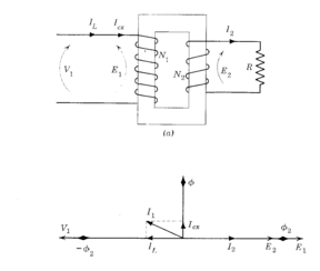
Imagine a toroid (donut shape) made of powdered iron. The toroid is the classic shape used in deriving magnetic formulas. Now wind a few turns of wire through the hole and call this the primary winding. We now have an inductor, and let us imagine that it is an ideal inductor?no resistance and no leakage flux, i.e., all magnetic flux lines are contained in the iron core. Also assume that the magnetic properties are linear, i.e., no hysteresis.

Here is a transformer made with a square donut.

trans.gif


Now apply a sinusoidal voltage. This creates a sinusoidal magnetizing current which creates a sinusoidal magnetic flux in the core which induces a ?back emf? in the primary equal and opposite to the applied voltage. This limits the magnetizing current.

Let me emphasize that the magnetic flux "flows" around the inside of the toroid much like an electrical current. There is, in this ideal case, no flux outside the iron!

Now wind a separate winding through the donut and call it the secondary. The changing magnetic flux generated by the magnetizing current induces an emf in the secondary which is equal to:

E2 = E1 x N2/N1

Now apply a load to the secondary. The resulting secondary current will try to create additional magnetic flux in the core, but the primary current will increase as well and its magnetic flux will exactly cancel that of the secondary. The result is that the magnetizing current remains constant under all load conditions.

Let me also emphasize that, in this ideal case, both the primary and secondary windings see exactly the same magnetic flux created by the magnetizing current in the primary winding.

Now I cannot explain the unseen mechanism that makes all this work. It is like explaining gravity. It just happens.

Of course a real transformer behaves a bit differently, but the ideal transformer is quite useful in understanding the basics. When all this sinks in, I will post the equivalent circuit of a real transformer.

[ August 26, 2005, 06:21 PM: Message edited by: rattus ]
 
Re: Transformer Primary Impedance

I have no idea how the magnetics work but it seems like the primary regardless of everything else needs to to keep the primary saturated with magnetic flux.And when this energy is removed by doing the work of magnetizing the secondary it tries to replace it.Make sense?

Rattus I was tying the same time you where I am just now reading your post.

[ August 26, 2005, 05:15 PM: Message edited by: ronaldrc ]
 
Re: Transformer Primary Impedance

Rattus I have a little different twist than that.
I think the energy in the magnetized iron core is used up or dissapated in magnetizing the secondary and in turn doing its work and the primary just tries to replace it.Are we on the same page? :)
 
Re: Transformer Primary Impedance

Hey Rattus you brought the subject up.

But if we made transformer laminations round like a donut would they be more efficient? :)
 
Re: Transformer Primary Impedance

Ronald,

Transformers have been made with coiled laminations--something like a clock spring, but I think the problems in winding would preclude their use as a power transformers. Toroids are wound by loading the wire on a bobbin and then winding the wire on the toroid--tricky.

I do think though that a toroid would provide the minimum leakage reactance.

The energy delivered by the primary current is transferred to the load via the magnetic flux and the secondary current--no core loss in an ideal transformer.

And, you NEVER want to SATURATE the iron because at that point its magnetic properties go to pot.
 
Re: Transformer Primary Impedance

I understand Rattus maybe I used the wrong term when I said saturate but I meant magnetize to the max without overheating. I did not know that are you certain?

If anyone wants to know what rattus is talking about next time you change a GFI receptacle out break the old one open thats what they use for the CT. or current transformer.

Ronald :)

[ August 26, 2005, 07:28 PM: Message edited by: ronaldrc ]
 
Re: Transformer Primary Impedance

Originally posted by ronaldrc:
I understand Rattus maybe I used the wrong term when I said saturate but I meant magnetize to the max without overheating. I did not know that are you certain?

Ronald :)
I am certain Ronald. Power transformers are designed to operate close to saturation, but not too close. Note that the primary voltage determines the magnetizing current. If you wired 240V to a 120V primary, you would almost certainly saturate the core and fry the primary.

Of course, in an ideal transformer, there would be no saturation or core loss.

BTW, You should go back to my post on page 2 to see the basic transformer diagram I have posted.
 
Re: Transformer Primary Impedance

Rattus I am glad you have a place you can post your graphics

I think our understanding of the transformer is in aligned with most in this field or related fields.

I started to say in my original post that it is theory and on one understands the magnetic coupling, would that be a fair statement?


Great graphic

Ronald :)

[ August 26, 2005, 10:09 PM: Message edited by: ronaldrc ]
 
Re: Transformer Primary Impedance

Hey, I notice Rattus has image capability. This is good, I expect the forum should experience an over all incrimenting from this developement. :cool:
 
Status
Not open for further replies.
Top