Transformer to transformer bonding 208Y to 480Delta

8sparky8

Member
Location
Columbus, OH
Occupation
Project Manager
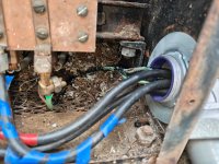
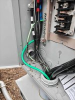
Hi all, I am not a transformer guy, so admittedly in over my head but I want to get this right for the customers sake. The customer has an old 3ph 30kva 208Y to 480D transformer next to the main service. We replaced the main service and installed a breaker panel that we then tied the transfer to on a 3 pole 100A breaker. Originally the #4 bond wire from the ground rods was tied to the XO on the transformer. When we replaced the service, we added a #4 in our conduit and bonded it in the breaker panel. I just read an old thread on here detailing why that is a bad idea, as the unbalanced load from the 480 side goes back onto the XO. They are having bad voltage on the load side and when I got there, the ground wire was melted between the XO and the breaker panel. So I know I need to remove the bond from the XO and only install it on the frame of the transformer. Why is/did the bond wire going to the ground rods not have any issues?

OK, now for the real question. The other side is going to another 37.kva 208y to 480 delta transformer that then drops the voltage back down to 208 and that feeds a breaker panel for a small house. They did this to limit the voltage drop as the distance between the two transformer is significant. Running between the transformers is just 3 conductors. How should the transformer at the other end be bonded?

Here is is in short hand:

100amp three pole breaker feeding 208v going 10ft to 208y480d transformer from there it is 3 wires from going 700ft to 800ft to a small house to another 208y / 480d transformer then 20 feet to a breaker panel.

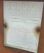
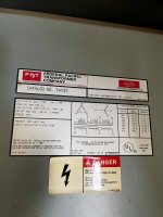
The old label is the transformer at the service, and the FPT is the transformer at the house (load side)

Can you confirm what the bonding should look like at both transformers so this is electrically safe and performs correctly.

This is a camp so lots of people coming and going who stay in the house this is serving.

Thanks for your help!
 

Attachments

  • IMG_20251022_145305005.jpg
    IMG_20251022_145305005.jpg
    564.1 KB · Views: 12
  • IMG_20251111_115150.jpg
    IMG_20251111_115150.jpg
    823.1 KB · Views: 12
  • IMG_20260318_163156329.jpg
    IMG_20260318_163156329.jpg
    655.7 KB · Views: 11
  • IMG_20260318_163841434.jpg
    IMG_20260318_163841434.jpg
    524.6 KB · Views: 9
  • IMG_20251022_145943389.jpg
    1 MB · Views: 2
Do you have an electrical contractor working on this?

If you are reverse feeding the first transformer NOTHING should be connected to the X0 terminal.
Yes. I am the electrical contractor. I just have not done a lot of transformers. At least not a lot of reverse feeding them.

Okay so I will remove everything from the XL on the reverse fed transformer and only Bond the frame. What about the transformer at the house 800 ft away which is not reverse fed it is going 480 back down to 208. Am I correct that that one should have XO going to my breaker panel and bonded everything hooked up as normal?
 
First the 'zeroth' question: do you _really_ need the step-up...long distance...step down arrangement? Yes, it does help with voltage drop, but it may be that with current loads you don't actually have a voltage drop problem.

There should be _nothing_ connected to X0 on the source end.
One of the terminals H1, H2, or H3 should be grounded, and connected to the EGC that should run with your 480V feeder. I do not believe that current code permits you to use the grounded conductor in lieu of the separate EGC, and if the system was not installed properly before you may not be 'grandfathered' to use the grounded conductor in lieu of a separate EGC.
You should have OCPD protecting the output of your transformer.

At the destination end X0 should be grounded and connected to the EGC of your destination system.
The destination transformer needs secondary OCPD, and may be required to have a local disconnect for the primary.

Ok, the way this is ideally done:
At the 'source end' you should have a 208V delta to 480/277V wye transformer.
You ground/bond the neutral on the 480/277V side.
You have OCPD on the secondary side.
You run 3 wires + EGC to the 'destination end'.
At the 'destination end' you should have a 480V delta to 208/120V wye transformer.
You have a primary disconnect for the transformer.
You have secondary OCPD for the transformer.
You ground/bond the neutral on the destination 208/120V side.

But you don't have the equipment for doing this ideally.
100% agree this current setup is not good. But I had no part in that, I replaced the 600amp service feeding the camp when the pole blew down in a storm. Then rebounded the transformer...wrong...and here we are!

Ok...I just pulled up to the job ...the customer informed me that he has 260 people coming for a week long event in about 6 hours ...my concern of course is safety. I will remove all from XO. As you can see by the pictures there is no ground running with the 480v feeder and I believe it is direct burial so I can't change that. I will remove all from XO and bond the frame and check the transformer by the house. I will update shortly. Please let me know if from a safety standpoint there is anything else I need to do.
I really appreciate all the help, you guys are awesome!
 
Yes. I am the electrical contractor. I just have not done a lot of transformers. At least not a lot of reverse feeding them.

Okay so I will remove everything from the XL on the reverse fed transformer and only Bond the frame. What about the transformer at the house 800 ft away which is not reverse fed it is going 480 back down to 208. Am I correct that that one should have XO going to my breaker panel and bonded everything hooked up as normal?
Yes
 
As you can see by the pictures there is no ground running with the 480v feeder and I believe it is direct burial so I can't change that. I will remove all from XO and bond the frame and check the transformer by the house. I will update shortly. Please let me know if from a safety standpoint there is anything else I need to do.
I really appreciate all the help, you guys are awesome!

Is the 480V grounded at all, or is it just 'floating'? Does it have a circuit breaker or fuses protecting the secondary of the first transformer?
 
Where did you land the GEC at the service? - The GEC should be landed on neutral bar of the service. NEC 2023 - 250.24(A)(4)

You need to make sure you bonded all the right stuff at the right locations. Do you have photos of how everything was wired before you started the job? Do you have better photos, zoomed a little further out, at the transformer? It looks like the green conductor is landed on the same bus the blue conductor is.

What was the measured voltages and where did you measure them at?

Since I don't see a green screw at the panel in the photo and I doubt it is a wire type MBJ I am a little worried about your understanding of grounding and bonding for services. Setting aside the issues you may have with transformers.

Did you call for inspection? The inspector might be able to call out your corrections to help you fix it.
 
The devil is in the details but, since you inherited this, on the "service side" you do not want XO to be connected to anything. Simply bond the transformer frame. At the cabin, be sure XO on the secondary is bonded and connected to a grounding electrode system. Check your voltages and be sure you have 120 to ground. There are areas that need addressing but that would relieve your immediate concern.
 
I agree with the others devil is in the details, like what the calculated load this is serving?
If I were looking at it I probably recommend a new transformer and keeping the existing 3-wire TN-C feeder, (presuming its grandfathered) I'd do a 208 Delta : Delta on the service end and a Delta : wye on the load end.
if its up to me I say always better to go with 600VAC for transmission lines, 480V is a good voltage for a industrial plant, but on a transmission line you want every last volt.
 
Do you have an electrical contractor working on this?

If you are reverse feeding the first transformer NOTHING should be connected to the X0 terminal.
An incomplete sketch is easier than trying to describe it.

The X0 connection at the first xfmr is optional.

Did not show OCPD at secondary of first xfmr, or both sides of second transformer but they need to be there as well.

There are other details that are necessary as well for a safe and code compliant installation. This focuses just on the four wires going from one xfmr to the next.

I do not see a code compliant way to not have four wires running between the xfmrs.


1773965780647.png
 
Last edited:
One other little detail. You need to extend the incoming G at the second transformer to the PB ground bus.

You could alternately make the N-G bond at the second xfmr at the panelboard. But only one of them.
 
If you say so.
But....... everything I have read and many experienced posters here say you should NEVER connect X0 on the primary side.
i would ask why?

If it is a delta source, I agree it is inappropriate to connect anything to the X0 terminal in this scenario. But we have a Wye source here.

One can argue it is somehow better, but its not a code violation as best I can tell.
 
If it were me ordering stuff I'd have ordered a delta to wye for the step up to the transmission line / feeder, I would not send a neutral with the TN-S feeder but it would have a grounded wye source then I dont need ground detectors or stright rated breakers etc, then at the destination end delta to wye for the step down. I agree its not a code violation to have the wye to delta at the source but you'd either ground a phase (TN-S) or have ground detectors (IT)
 
i would ask why?

If it is a delta source, I agree it is inappropriate to connect anything to the X0 terminal in this scenario. But we have a Wye source here.

One can argue it is somehow better, but its not a code violation as best I can tell.
I'm not and engineer or have that much theory under my belt. I'm just going off of what I have heard over my 43+ years in the trade and what i had read on this forum over the ~25 years I have been a member here. Maybe I have understood it incorrectly. Maybe some other members will chime in. In this thread Winnie also said it should not be connected.
 
I have never used a wye primary on the step up side, its not a violation, the violation comes from the ungrounded (IT) delta secondary or not using a breaker rated for a corner ground system if the delta has one phase grounded.
 
I have never used a wye primary on the step up side, its not a violation, the violation comes from the ungrounded (IT) delta secondary or not using a breaker rated for a corner ground system if the delta has one phase grounded.
I had not thought about that issue. But as my post to the guy mentioned, I was focused mostly on needing four wires running between the transformers. I see no way to do this that is code compliant with only three wires.
 
i would ask why?

If it is a delta source, I agree it is inappropriate to connect anything to the X0 terminal in this scenario. But we have a Wye source here.

One can argue it is somehow better, but its not a code violation as best I can tell.

It isn't an absolute rule that you shouldn't connect a supply neutral to the X0 of a transformer primary, but in general it is a very bad design in common situations.

The issue is specific to transformers with a wye primary and a delta connected set of coils. This combination means that the transformer defines a low impedance neutral, meaning that the neutral voltage is in fixed relation to whatever is connected to X1, X2, and X3, set by the transformer.

This well defined neutral is precisely why we use delta:wye transformers to derive systems with a neutral in the first place.

If you connect the neutral of a wye primary to the neutral of a supply, then your transformer will 'compete' with the supply system to define the neutral.

Say you have a 208/120V system with uneven loading and uneven voltage drop. Current will flow into your wye primary as it attempts to rebalance that voltage drop.

Sometimes utility companies will intentionally do this to better define the L-N voltage on their transmission lines.

But the bad situation (what happened to the OP) is you have a small wye:delta transformer trying to control the neutral voltage on a larger system. You get circulating currents that damage the transformer or the neutral connection.

So you don't connect a supply neutral to X0 of a wye primary delta secondary transformer unless you intentionally want and design for the neutral balancing effect.

Also note that things are different with wye:wye transformers.
 
The devil is in the details but, since you inherited this, on the "service side" you do not want XO to be connected to anything. Simply bond the transformer frame. At the cabin, be sure XO on the secondary is bonded and connected to a grounding electrode system. Check your voltages and be sure you have 120 to ground. There are areas that need addressing but that would relieve your immediate concern.
Since he states 480D in the first post, I would assume there isn't an XO on the secondary side. I assume though that there is no need, but also no problem with connecting the neutral from the service (208/120) to the XO.
 
Top