They receive just V. The PF and I is what the motor makes of it.
a motor will not run without i
They receive just V. The PF and I is what the motor makes of it.
Correct.a motor will not run without i
Correct.
The motor consumes I. It is not forced upon it as I'm sure you know.
So let me ask this, because I’m not sure how to measure it and what the consequences would be. Maybe you guys do?
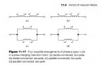
In high speed we are bringing back the T1, T2, and T3 connections, with #2 wire that has read too hot on IR scans dating back to 2002, and shorting these three wires together. Now at the starter end how do we measure what the voltage drop on these #2 conductors are? If it is found to be excessive what symptoms will be displayed? If allowed to go on long enough what harm may happen?
Seems to me best we can do is compare currents. T1 and T6 should have the same current, correct? The degree of imbalance would only be attributable to difference in winding and/wiring impedance, correct? Trying to wrap my head around if both currents should sum to zero even.
Quite true. Not sure what was up with the shop vs site pf stuff. Kinda weird but maybe I missed his point.They receive just V. The PF and I is what the motor makes of it.
Have you considered some aux cooling to get you by until it can be taken out of service? Additional cooling can forgive a multitude of sins...for a little while anyway.Thank you Sir. I believe it's going to be sent out again anyway whether we really want to or not as it's getting hot enough to cook eggs on. It's also producing that old familiar burnt winding smell.
It won't have i until there is V applied.a motor will not run without i
How is this motor wound in comparison to a typical 9 lead dual voltage motor? No way you change the number of poles in those when you configure in two parallel wye's for low voltage operation, if you did you wouldn't have same speed at high/low voltage.yep
lo they are in series you have 8 poles
in hi they are paralleled, ie, you pair up poles (ie by phase) so result is 4
in the basic diagram each coil is actually 4 pole pairs (8 poles)
that is cut in half when paralleled
OK. Motor receives just voltage. It is just another connected load to a common voltage supply. The supply power factor is not an issue.it consumes power, actually converts
the i that enters = the i that leaves, kcl, which means no i is 'consumed'
as you know
All the drawings so far are showing same coils just connected in different manners, still using all of the coils in all the different configurations, how does that change number of poles?
Change in number of poles would definitely change speed but that isn't what we have here. All we are doing here is changing voltage applied across each coil and therefore not producing as much torque in some configurations as others, which results in more slip.
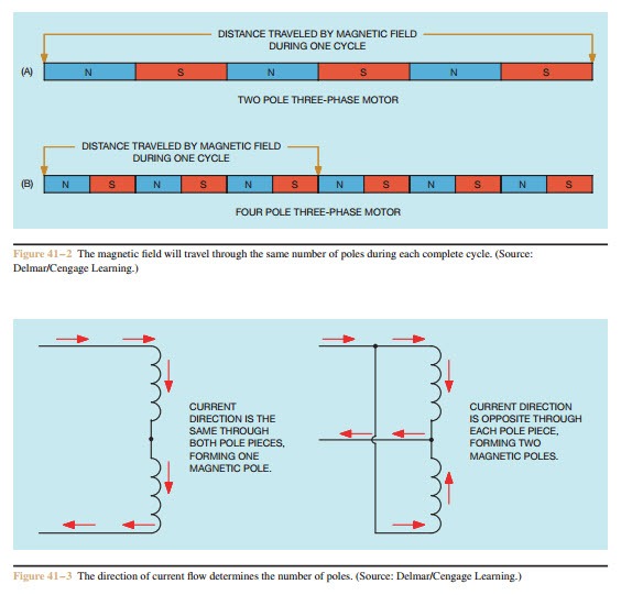
Thanks, didn't look at any of your links, but the figure 41-3 was enough to make the right thing click in my brain when it comes to how many poles there can be in the stationary windings.Have a look at these pages for a basic explanation.
https://en.wikipedia.org/wiki/Dahlander_pole_changing_motor
http://machineryequipmentonline.com...ole-motorsthree-speed-consequent-pole-motors/
MTW
OK. Motor receives just voltage. It is just another connected load to a common voltage supply. The supply power factor is not an issue.
It won't have i until there is V applied.
How is this motor wound in comparison to a typical 9 lead dual voltage motor? No way you change the number of poles in those when you configure in two parallel wye's for low voltage operation, if you did you wouldn't have same speed at high/low voltage.
no it doesn.t
receives v, I at a pfa and their product power, both active and reactive
So does it produce or receive V? you have separately stated it does both.it will not produce v until I flows
So does it produce or receive V? you have separately stated it does both.
no it doesn.t
receives v, I at a pfa and their product power, both active and reactive