Unbalance neutral current in a 3 phase system

Status
Not open for further replies.

crossman

Senior Member
Location
Southeast Texas
Thank you Charlie B. That helps.

I just read something that made me realize this: (I will use a current phasor as an example) I had been making the mistake of thinking of the phasor itself as the actual current. But it is not. The actual (real) current is the projection of the phasor onto the horizontal axis. The projection of the phasor onto the vertical axis is the "imaginary" part and isn't "real". I'm not sure of the physical meaning of this, but combined with the real horizontal component, it defines the phase angle of the current. So now I am totally content that the phasor operates in the complex plane and contains both real and imaginary parts. The phasor does not operate in the normal 2 dimensional or 3 dimensional coordinate systems.
 

rattus

Senior Member
Crossman,

A static phasor is a complex number which provides the RMS magnitude and phase angle of an AC voltage or current, and this complex number is a constant; it does not vary. Time and frequency are not factors here, although frequency is a factor in impedances.

Static phasors are used with impedances to perform AC analyses.

The phasor may be represented in several way--polar, rectangular, trigonometric, exponential, graphical....

In the graphical representation, the length of the arrow is proportional to the RMS magnitude, and the angle between the arrow and the horizontal axis is the phase angle. The projections on the two axes are given by,

Vrms(cos(phi)) and Vrms(jsin(phi))

These values have no special meaning.

Rotating phasors ARE functions of time and frequency, but let's not get into that just now.
 
It still works

It still works

Roger,
I just went to the lab and ran the numbers you provided and when:
A=20, B=20A and C=0A the result is 13.3A

When A=20A and B=20A and C=10A the result is 5.8A

Which is the actual result of the calculation using the square root of 3.

Thanks,
Gary
 

rattus

Senior Member
Something wrong here:

Something wrong here:

Gary Shumaker said:
Roger,
I just went to the lab and ran the numbers you provided and when:
A=20, B=20A and C=0A the result is 13.3A

When A=20A and B=20A and C=10A the result is 5.8A

Which is the actual result of the calculation using the square root of 3.

Thanks,
Gary

For Ia = Ib = 20A, and Ic = 0,

In = 20A

If we have a balanced system and disconnect one phase, the neutral currents makes up for the missing phase current.

In the second case,

In = 10A
 

charlie b

Moderator
Staff member
Location
Lockport, IL
Occupation
Semi-Retired Electrical Engineer
Gary Shumaker said:
I just went to the lab and ran the numbers you provided and when:
Gary Shumaker said:
A=20, B=20A and C=0A the result is 13.3A. When A=20A and B=20A and C=10A the result is 5.8A. Which is the actual result of the calculation using the square root of 3.
I don’t know how you set up your lab test, but what you are describing is nonsense.

First, if you have a three phase WYE system, and if the phase currents are 20, 20, and 0, then the neutral current will be 20, not 13.3. Also, if the phase currents are 20, 20, and 10, then the neutral current will be 10, not 5.8. So you are doing something wrong in the lab.

Secondly, I think you are incorrectly adding and subtracting values for currents. Your line, “delta phase A - phase B” will have no meaning, if you simply use numbers for the currents. The current in one phase differs from the currents in the other two by virtue of the phase angles between them. You are subtracting apples from oranges. Suppose you measure,in the lab, phase A current at 20 amps and phase B current at 15 amps. The phase A current is not just “20 amps,” it is “20 amps at a phase angle of 0 degrees.” The phase B current is not just “15 amps,” it is “15 amps at a phase angle of 240 degrees.” You cannot subtract them by simply taking 20-15=5.
Gary Shumaker said:
(I1+I2+I3) divided by 1.73 = neutral current. This method proved out in the lab.
This set of equations gives you the average value of the difference between phases. You are taking A-B and dividing by the square root of 3. Then you are taking A-C and dividing by the square root of 3. Finally, you are taking B-C and dividing by the square root of 3. When you add these and divide again by the square root of three, what you are left with is the following:
{ (A-B) + (A-C) + (B-C)} / 3. That type of equation gives you an average value, and has nothing to do with the net imbalanced current in the three phases.

The right way to calculate neutral current is the equation that Roger gave in post #2.
 

crossman

Senior Member
Location
Southeast Texas
Another correct way is to do the method in Post 3.:grin:

I also did the experiment in the lab. Now, my lab equipment won't handle the 20 amps, so instead of 20, 20, 0 and 20, 20, 10, I used 2, 2, 0 and 2, 2, 1. Same thing, just multiply by 10 to get the answers.

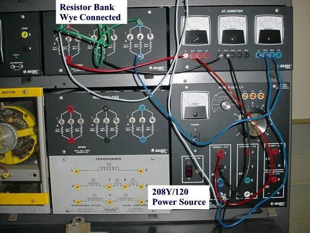
First photo = lab setup
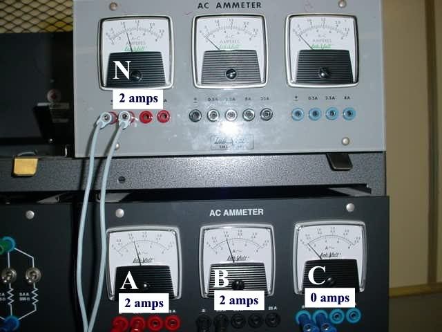
Second photo = meters with 2 amps, 2 amps, 0 amps with neutral = 2 amps
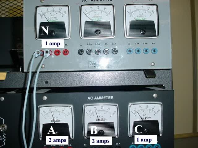
Third photo = meters with 2 amps, 2 amps, 1 amp with neutral = 1 amp

metersetupA.jpg


meter20200.jpg


meter202010.jpg


http://i173.photobucket.com/albums/w70/garygauge/meter202010.jpg?t=1198007824
 
Last edited:

crossman

Senior Member
Location
Southeast Texas
Rattus:

Consider this thought:

The magnitude of the rotating phasor for voltage must equal the peak value.

The magnitude of the static vector for voltage must equal the RMS value.

Any validity?
 

rattus

Senior Member
You got it!

You got it!

crossman said:
Rattus:

Consider this thought:

The magnitude of the rotating phasor for voltage must equal the peak value.

The magnitude of the static vector for voltage must equal the RMS value.

Any validity?

True for current also.

In either case though, the preferred term is "phasor".
 

rattus

Senior Member
An Observation:

An Observation:

It should be noted that either of the problems in this thread can be solved by observation. In general though, one should use the algebraic formula if the PFs are approximately equal.

In the first, In must balance the two phase currents, therefore its magnitude is 20A. It matters not to Kirchoff whether this is a phase current or neutral current.

In the second, we can visualize a 10A balanced wye which we can remove from the problem leaving phase currents 10A, 10A, and 0A. Now we have the same scenario as in the first problem, therefore In = 10A.
 

crossman

Senior Member
Location
Southeast Texas
Rattus, thanks for your time and effort. I am realizing things which I had not thought of before. For instance, I never considered that there was a static RMS phasor and a rotating peak value phasor. The complex plane idea, I can accept that now, because it is needed for the multiplication of the phasors to work out. Not that I have figured out how to multiply phasors!

Charlie B, thanks also for your help.

Sorry to be such a P.I.T.A. about this stuff, but it does interest me.
 

rattus

Senior Member
crossman said:
Rattus, thanks for your time and effort. I am realizing things which I had not thought of before. For instance, I never considered that there was a static RMS phasor and a rotating peak value phasor. The complex plane idea, I can accept that now, because it is needed for the multiplication of the phasors to work out. Not that I have figured out how to multiply phasors!

Charlie B, thanks also for your help.

Sorry to be such a P.I.T.A. about this stuff, but it does interest me.

Glad to do it Crossman. I appreciate someone who asks questions when they don't understand.
 
Your set up is missing the neutral current meter.

Your set up is missing the neutral current meter.

crossman said:
Another correct way is to do the method in Post 3.:grin:

I also did the experiment in the lab. Now, my lab equipment won't handle the 20 amps, so instead of 20, 20, 0 and 20, 20, 10, I used 2, 2, 0 and 2, 2, 1. Same thing, just multiply by 10 to get the answers.

First photo = lab setup
Second photo = meters with 2 amps, 2 amps, 0 amps with neutral = 2 amps
Third photo = meters with 2 amps, 2 amps, 1 amp with neutral = 1 amp

metersetupA.jpg


meter20200.jpg


meter202010.jpg


http://i173.photobucket.com/albums/w70/garygauge/meter202010.jpg?t=1198007824

From: Gary,
I have the exact lab set up equipment. What I don't see in your set up is a current meter from the vitual neutral (green wires). If you run a wire from the wye connection (green wires) through a currrent meter and return it to the white connection you will see the actual unballanced current value.
Good job though.
Kind regards,
Gary
 
required expression for 3 phase calculations

required expression for 3 phase calculations

Hi guys,
May humbly point out that whenever 3 phase current calculations are expressed, √3 is always used (1.732). If you lean more toward the engineering level of calculating you might prefer the sine of 120 degrees (0.886).

In my equation I divide each phase current difference by √3 then add the results and divide the result by √3 to obtain verifiable results. I have changed the currents to many different values and still came up with the calculated results in the lab.
Also, I don?t know how many of you know John Sitz but he also agrees with my calculation.
Meanwhile, I thank you all for the great and thoughtful input.
Kind regards,
Gary Shumaker
 

roger

Moderator
Staff member
Location
Fl
Occupation
Retired Electrician
Gary, I hope this is not what you are teaching. As said earlier by an engineer "what you are describing is nonsense".

Forgetting the rest of us, you have had two engineers in this thread tell you the correct answers and they showed you how to calculate this for the correct answers.

Roger
 

crossman

Senior Member
Location
Southeast Texas
Gary Shumaker said:
What I don't see in your set up is a current meter from the vitual neutral (green wires). If you run a wire from the wye connection (green wires) through a currrent meter and return it to the white connection you will see the actual unballanced current value.

In the first photo, the two light blue wires which run vertically out of the picture are going to the Neutral ammeter.

Take a careful look at the light blue wire. It comes from the neutral of the power supply, runs up to the ammeter at the very top marked with an N in the second and third pic. From there, it runs to the neutral side of each resistor bank. The two green jumper wires complete the wye connection.

Here is a drawing of the experiment. I am 100% positive that it is connected correctly and I am 100% positive that the vectors, the formulas, and the results are correct.

Edit: I have also added a composite photo of the experiment showing the neutral meter in the entire arrangement.

Picture1.jpg


Picture7.jpg
 
Last edited:

crossman

Senior Member
Location
Southeast Texas
Gary,

I am with Roger. Go back and read this thread!

Algebra does not lie. Your formula and method is completely incorrect.

How about going back and doing your calculation for us again, using

208Y/120
A phase amps = 20
B phase amps = 20
C phase amps = 10
What is neutral current?

Edit: Are you yanking our chain on this, just having a little fun at our expense?
 
roger said:
Gary, I hope this is not what you are teaching. As said earlier by an engineer "what you are describing is nonsense".

Forgetting the rest of us, you have had two engineers in this thread tell you the correct answers and they showed you how to calculate this for the correct answers.

Roger

Roger,
As far as teaching methods using the square root of 3, it is well known throughout the industry that to find the current given the VA and V the formula to find current is VA divided by (√3 x V). Also, to find the value of the high leg on a delta-tapped transformer secondary you multiply the voltage between one of the lines and the tap by √3 (e.g., 120 x 1.732 = 208).

This has been a discovery issue for me and so far I have been polite to all. I have over 40 years of engineering experiences so please don?t assume that I am completely without a clue. However, even with 40 years engineering experience there is always something new to learn and I have greatly appreciated all of the information given. Some solutions have been very complex and are way beyond what my students will understand. Also, I am a big fan of Acums(sp) razor, ?The simplest solution is usually correct.?
One of the first solutions given (I think it was yours Roger) came the closest to accuracy but when tested in the lab, a large variations of the currents caused some inaccuracies in the formula.
I any case, thank you again (all of you) for your valuable information.
Gary Shumaker
 

crossman

Senior Member
Location
Southeast Texas
Gary, I hope you aren't bailing out of this thread yet. We really need to straighten this out, either we are wrong or you are wrong. And if I am wrong, I absolutely want to know so I can change my methods.
 

roger

Moderator
Staff member
Location
Fl
Occupation
Retired Electrician
Garry, although 120 x 1.732 will give you the sum of 208 that is not really the correct way to think of the high leg votage in a delta.

ED's4Wdelta2.JPG


And here is another example of your neutral current question.

410ecm06fig4.jpg


Roger
 

LarryFine

Master Electrician Electric Contractor Richmond VA
Location
Henrico County, VA
Occupation
Electrical Contractor
crossman said:
How about going back and doing your calculation for us again, using

208Y/120
A phase amps = 20
B phase amps = 20
C phase amps = 10
What is neutral current?
10a. That's easy to explain using just words.

If you start with the balanced 20/20/20a loading, and no neutral current (with which we all agree, no?), any current you subtract from one phase causes the neutral current to rise by the exact same amount.
 
Status
Not open for further replies.
Top