Unbalance neutral current in a 3 phase system

Status
Not open for further replies.

rattus

Senior Member
Smart $ said:
Ummm... if you would be so kind as to give an expanation of the vectors in your diagram. As far as I can tell, they do not correlate to anything in the post you quoted.

Smart, he has scaled the drawings to 1A/inch.
 

jghrist

Senior Member
weressl said:
Could somebody untagle why the vector solution gives 1.79333A
It's because you created the unbalance by shifting the neutral instead of extending the phases. You end up with angles between phases that are not 120?, which is a necessary condition for the sqrt(A?+B?+C?-A?B-B?C-A?C) equation to work.
 

Smart $

Esteemed Member
Location
Ohio
rattus said:
Smart, he has scaled the drawings to 1A/inch.
I assumed that. However, it didn't sink in what Laszlo was attempting to do until I revisited his diagram just now. He's plotting the equidistant point from the ends of the three vectors.
 

Smart $

Esteemed Member
Location
Ohio
weressl said:
Could somebody untagle why the vector solution gives 1.79333A
As mentioned in my response to rattus, I gather you are plotting the equidistant point from the end of the three vectors. It don't work :wink:

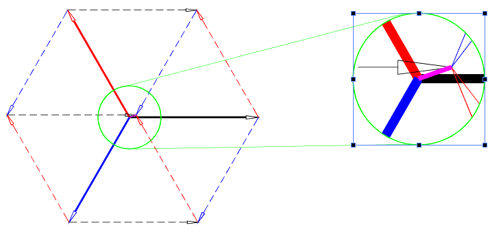
Consider the following diagram. I have the base vectors in the middle, emanating from coordinate 0,0. In order to vectorially add these vectors they have to be arranged tail to head. Doing so can be done six different ways, or as in the diagram, utilizing all six. In the latter case, note how the result appears to be a slightly skewed isometric view of a cube.

Anyway, rattus is wrong about the phase angle of the resulting neutral current vector?which is 2.65A @ 199.1?.

NOTE: Because of the scale of the drawing versus the length of the neutral vector my diagram has no arrowhead on the neutral vector (the fuscia colored line).

neutralcurrent.gif
 

rattus

Senior Member
Smart, I give you credit for figuring out what Laszlo was doing, but you are making this problem unbelievably complicated. All you need do is draw out the three phasors, head to tail, like a delta, then close the diagram with a fourth phasor which is In.

But, this is a poor way to solve the problem because in this almost balanced system the neutral phasor is so short it is hard to measure. If you use graphics, you should reduce the problem as I have done. Then, you have the phasor sum of 1.732A @ 120 and 2A @ 0. The phase angle is clearly in the first quadrant. It is not 199 degrees.
 

Smart $

Esteemed Member
Location
Ohio
rattus said:
Smart, I give you credit for figuring out what Laszlo was doing, but you are making this problem unbelievably complicated. All you need do is draw out the three phasors, head to tail, like a delta, then close the diagram with a fourth phasor which is In.
I did that, but at the same time showed it can be done six different ways!!!

So what do you have in your reference texts that say I can't do that?

But, this is a poor way to solve the problem because in this almost balanced system the neutral phasor is so short it is hard to measure. If you use graphics, you should reduce the problem as I have done. Then, you have the phasor sum of 1.732A @ 120 and 2A @ 0. The phase angle is clearly in the first quadrant. It is not 199 degrees.
I have no idea where you are getting "the phasor sum of 1.732A @ 120 and 2A @ 0". :rolleyes:

Earlier you said it was "3A @ 0" and "2A @ 120".

The 3A @ 0? is good, but the other should be 1A @ 120?—the result of removing the balanced portion of the circuit: 46A from all three. Therefore we have

49A – 46A = A' = 3A @ 0? = 3 + j0
47A – 46A = B' = 1A @ 120? = -0.5 + j0.866
46A – 46A = C' = 0A @ 240? = 0 + j0

The sum is 2.5 + j0.866 and represents the point at the tail end of neutral vector. The head end of neutral vector is at 0 + j0.

(0 + j0) - (2.5 + j0.866) = -2.5 - j0.866 = 2.65 @ 199.1?
 
Last edited:

rattus

Senior Member
Yer right Smart:

Yer right Smart:

That is what I get for trying to do too much in my head! I should have said that In is the sum of the two phasors,

2A @ 120
3A @ 240

then,

In = -2.5 -j0.866 = 2.65A @ 199.1

You actually found the negative of In and took the liberty of negating it again to get the right phase angle.

"The sum is 2.5 + j0.866 and represents the point at the tail end of neutral vector. The head end of neutral vector is at 0 + j0."

This gets the right answer, but strictly speaking is incorrect. You should have said the sum is the negative of In and then negated it.

I believe though that we agree that the sum of ALL currents either into or out of the neutral node is zero. That is, In is that current which will satisfy Kirchoff's current law. We could have defined In as the sum of the phase currents. I am unaware of any rule or convention though. How about you?
 

Smart $

Esteemed Member
Location
Ohio
rattus said:
...You actually found the negative of In and took the liberty of negating it again to get the right phase angle.

"The sum is 2.5 + j0.866 and represents the point at the tail end of neutral vector. The head end of neutral vector is at 0 + j0."

This gets the right answer, but strictly speaking is incorrect. You should have said the sum is the negative of In and then negated it.
To simply state IN as "the sum is the negative of In" does not prove such. I offered simple proof. Rejection of said proof is your prerogative, just like it is my prerogative to respectfully disagree regarding its correctness.

I believe though that we agree that the sum of ALL currents either into or out of the neutral node is zero. That is, In is that current which will satisfy Kirchoff's current law. We could have defined In as the sum of the phase currents. I am unaware of any rule or convention though. How about you?
Same here.
 
Last edited:

rattus

Senior Member
Smart $ said:
To simply state IN as "the sum is the negative of In" does not prove such. I offered simple proof. Rejection of said proof is your prerogative, just like it is my prerogative to respectfully disagree regarding its correctness.


Same here.

Smart, we agree on the result, right? I am simply saying that,

2.5 +j0.866 = 2.65A @ 19.1 = -In

Negate that phasor to obtain,

In = 2.65A @ 199.1

In other words, after applying Kirchoff's current law,

In = -(Ia + Ib + Ic)

I approached the problem by finding the the sum of the currents necessary for balance. Then I didn't have to negate.

You slipped the negation in without fully explaining it. Your phasor diagram would look funny with the arrowhead at the origin.
 

Smart $

Esteemed Member
Location
Ohio
rattus said:
Smart, we agree on the result, right? I am simply saying that,

2.5 +j0.866 = 2.65A @ 19.1 = -In

Negate that phasor to obtain,

In = 2.65A @ 199.1

In other words, after applying Kirchoff's current law,

In = -(Ia + Ib + Ic)

I approached the problem by finding the the sum of the currents necessary for balance. Then I didn't have to negate.
I'm OK with the above, as long as it is [mentioned and...] understood that your last formula is regarding the phasor relationship and not a simple algebraic equation. Without noting and comprehending such, someone could come along and calculate the problem as In = -(Ia + Ib + Ic) = -49A - 47A - 46A = -44A, which all us knowledgeable types know to be an incorrect result.

You slipped the negation in without fully explaining it.
Seems to me we're both coming up a little short on complete explanations :grin:

Your phasor diagram would look funny with the arrowhead at the origin.
In my mind it wouldn't :wink:

It meets the head to tail requirement of vector addition AND is accurately descriptive in the application of Kirchoff's current law.
 

rattus

Senior Member
Smart, I see where you are coming from now. How about one of your nice diagrams to help us visualize the method?
 

rattus

Senior Member
A little trick:

A little trick:

The algebraic formula,

In = sqrt(Ia^2 + Ib^2 + Ic^2 -Ia*Ib - Ia*Ic -Ib*Ic),

is a little tricky to evaluate even with a calculator. We can however simplify the problem greatly.

Subtract the smallest phase current from Ia, Ib, and Ic. This leaves two currents which we will call I1 and I2. Then,

In = sqrt(I1^2 + I2^2 - I1*I2)

From Smart's example, let I1 = 1 and I2 = 3, then

In = sqrt(2^2 + 3^2 - 3*2) = sqrt(4 + 9 - 6) = sqrt(7) = 2.65A
 

Smart $

Esteemed Member
Location
Ohio
rattus said:
Smart, I see where you are coming from now. How about one of your nice diagrams to help us visualize the method?
I'm not sure exactly what it is you want me to diagram.

As to negating IN, it is most obvious when stated initially as a vectorial equation conforming to Kirchoff's current law.
IA + IB + IC + IN = 0 vectorially
Therefore,
IA + IB + IC = ?IN vectorially

In a head to tail graphical representation, no matter where the first vector starts it will always be the same point where the last vector ends, i.e. the four vectors will form a quadrilateral [for those who don't know, a quadrilateral is a four-sided, closed polygon].
 

rattus

Senior Member
Thought I was wrong!

Thought I was wrong!

Smart $ said:
Anyway, rattus is wrong about the phase angle of the resulting neutral current vector?which is 2.65A @ 199.1?.

Smart, you tricked me. I was responding to Laszo's question where,

Ia = 46A
Ib = 47A
Ic = 49A

2.65A @ 40.9 degrees is correct.

You defined the currents as,

Ia = 49A
Ib = 47A
Ic = 46A

Magnitude doesn't change; angle does.
 

rattus

Senior Member
Do this, please:

Do this, please:

rattus said:
Smart, I see where you are coming from now. How about one of your nice diagrams to help us visualize the method?

Just give us a phasor diagram of the 3A, 2A, 2.65A closed polygon. I could do it, but your diagrams are prettier.

Picture worth a kiloword!
 

Smart $

Esteemed Member
Location
Ohio
rattus said:
Smart, you tricked me. I was responding to Laszo's question where,

Ia = 46A
Ib = 47A
Ic = 49A

2.65A @ 40.9 degrees is correct.

You defined the currents as,

Ia = 49A
Ib = 47A
Ic = 46A

Magnitude doesn't change; angle does.
I didn't trick you... Laszlo did with his diagram :D

He quoted the problem...
Gary Shumaker said:
...For example, if phase A = 49A and phase B = 47A and phase C = 46A...
 

Smart $

Esteemed Member
Location
Ohio
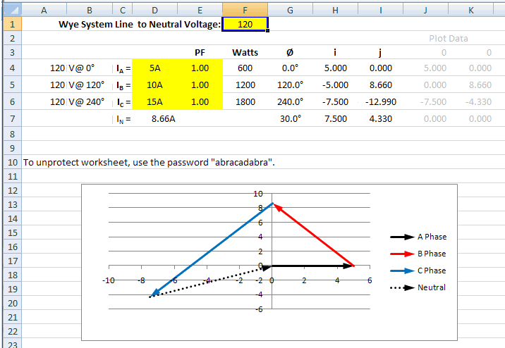
I revised my Excel calculator to also plot the vectors...

calculator.gif


Click here to download the Excel file (Excel 2007 converted to Excel 97-2003 format)

EDIT I discovered an error in my calculator. I had forgot that I was working with positive phase angles and subtracted the lag angle due to power factor. When working with positive angles the lag angle gets added... so I corrected the formula. If you downloaded prior to this edit, please download again.

I also re-formatted the diagram for a better appearance. I should note however, I have yet to find a method of scaling both axes the same, so the vector angles may be skewed somewhat. I considered making fixed scale axes, but then the vectorial representation may be too small or too big. To have the scale and angle relationships appear more accurate will require manual resizing of the "chart".
 
Last edited by a moderator:
Status
Not open for further replies.
Top