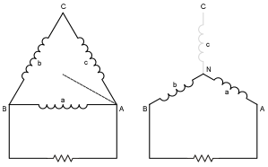
unbalanced 3 phase generator load

Status
Not open for further replies.

Besoeker

Senior Member
Location
UK

Smart $

Esteemed Member
Location
Ohio
... Please demonstrate none of the three windings has an overcurrent condition, where Iphase = "3?-Iline"/1.732.

I already gave an evidence of a generator manufacturer for the use of a delta connected three phase generator as a single phase generator at 57% of its three phase capacity in post#77.

:thumbsdown:

Okay.
Let us both try to apply the symmetrical components method to find whether that generator manufacturer is worthy of any business.
First the single phase load is connected only between any two terminals of the delta connected generator. So if the phase angle of current Iline from one terminal is taken as zero, the phase angle of the same return current through the other terminal should be taken as 180. The current through the third terminal is zero. So the negative sequence current I2 is given by

I2= [Iline(0)+(a*a)*Iline(180)]/3.............(1), where 'a' is complex operator.

Please calculate the value of I2 in (1) in terms of Iline to proceed further.

Gee, Sahib... I ask you a question about a simple resistor network and get nothing but subterfuge. And now you're asking me to do symmetrical component analysis... :blink:
Aww... what the heck.

Where VA is 0? phase reference...

Ia = |Iline| < 30?
Ib = |Iline| < -150?
Ic = 0 < 120?

Components:

I0 = 0 < 120?
I1 = 0.5774*|Iline| < 0?
I2 = 0.5774*|Iline| < 60?

Will someone please check my math :angel:, and please explain what the results mean in physical terms... :?
 

topgone

Senior Member
Aww... what the heck.

Where VA is 0? phase reference...

Ia = |Iline| < 30?
Ib = |Iline| < -150?
Ic = 0 < 120?

Components:

I0 = 0 < 120?
I1 = 0.5774*|Iline| < 0?
I2 = 0.5774*|Iline| < 60?

Will someone please check my math :angel:, and please explain what the results mean in physical terms... :?

You're math is correct but why do zero vectors have angles?

Basically, what you have are sequence vector sets, positive and negative. When you add those two sets of vectors, they will result into the initial line current values.
 

Smart $

Esteemed Member
Location
Ohio
You're math is correct but why do zero vectors have angles?
I know, totally superflous... but FWIW, I used a calculator which had boxes for line current phase angles. I entered 120? for Ic, and it returned 120? for I0.

Basically, what you have are sequence vector sets, positive and negative. When you add those two sets of vectors, they will result into the initial line current values.
Really?...!!! :roll::roll::roll:


I was looking more for how the result correlates to source windings' ratings.
 

Sahib

Senior Member
Location
India
Smart $:
Thanks for calculating the symmetrical components.
The positive sequence current component is
I1 = 0.5774*|Iline| < 0? from your calculation. Since it is balanced, the corresponding component in each phase winding is (0.5774*|Iline| < 0?)/1.732=1/3*|Iline| < 0?. The other component to add/subtract is the circulating current in the winding. I hope you would calculate that too. :)
 

Sahib

Senior Member
Location
India
Smart $:
Since the internal impedance of the generator is very low, the internal voltage drop may be neglected. In that case, the current in each phase of the generator may be taken as
1/3*|Iline|.
 

Smart $

Esteemed Member
Location
Ohio
... Since it is balanced, the corresponding component in each phase winding is (0.5774*|Iline| < 0?)/1.732=1/3*|Iline| < 0?.

I understand your assertion, but do not agree with the "each phase winding" part of it. In support of my disagreement, consider an equivalent rated wye source. Analysis of line current yields the same result. It is quite obvious the current in the C winding is 0. Yet for a wye, we can easily determine the line-to-line capacity for single phase loading is 57.74% (without thermal considerations :p).

I was also reading a similar topic over at eng-tips.com forum. I think it was jghrist that said you can't determine unbalanced delta winding currents with component analysis, or so I understood. But perhaps that is because circulating currents don't show in a line current analysis... which leads to your next comment and request.

The other component to add/subtract is the circulating current in the winding. I hope you would calculate that too.
What happened to consideration of I2, i.e. negative sequence... or is that what you are referring to, since you used the terminology "negative sequence circulating current" earlier. As I said earlier, that is not how I understand circulating currents... and they don't show in a line current component analysis.

Anyway, I either never learned or forgot. Either way, it amounts to, I don't know how to do what you are asking. So please enlighten me...

On a side note, regarding the similar topic over at eng-tips.com forum, there are three files at the end that posters uploaded to a file sharing site. I'd like to view those. Membership to the storage site was required and I joined using fake info, but then the downloading process involves installing some application(s)... which I do not want. I do not even want to install and uninstall on my computer. If anyone has access to those files and can provide a link to direct download, I'd appreciate it. Also, if you can obtain the files, but cannot provide a the means for direct download, PM me and I'll give you my email adrress so you can send 'em that way.
 

Smart $

Esteemed Member
Location
Ohio
Smart $:
Since the internal impedance of the generator is very low, the internal voltage drop may be neglected. In that case, the current in each phase of the generator may be taken as
1/3*|Iline|.
Depending on exactly what you mean by voltage drop, that'd be another assertion I do not agree with. The basis of my claim way back when (or so it seems at this point) is rooted in winding impedance... how can I neglect it if I am to (eventually?) make my point? (that's a redundant question BTW).
 

GoldDigger

Moderator
Staff member
Location
Placerville, CA, USA
Occupation
Retired PV System Designer
Depending on exactly what you mean by voltage drop, that'd be another assertion I do not agree with. The basis of my claim way back when (or so it seems at this point) is rooted in winding impedance... how can I neglect it if I am to (eventually?) make my point? (that's a redundant question BTW).
+1, especially since the internal voltage drop across the resistance of the windings is the largest source of energy losses in the generator and therefore is a potentially limiting factor for output.
 

Sahib

Senior Member
Location
India
I understand your assertion, but do not agree with the "each phase winding" part of it. In support of my disagreement, consider an equivalent rated wye source. Analysis of line current yields the same result. It is quite obvious the current in the C winding is 0. Yet for a wye, we can easily determine the line-to-line capacity for single phase loading is 57.74% (without thermal considerations :p).

In the subject delta connection also, the line current in terminal C is zero.

Whereas in delta connection it is phase current that is in dispute for determination 57% single phase capacity, in star connection it is phase voltage, because the 'neutral' of the single phase load connected between two lines does not coincide with that of the source and so how to ensure that the neutral of the source also not drifted, thereby applicability of factor 1.732 is ensured!
I was also reading a similar topic over at eng-tips.com forum. I think it was jghrist that said you can't determine unbalanced delta winding currents with component analysis, or so I understood. But perhaps that is because circulating currents don't show in a line current analysis...

Anyway, I either never learned or forgot. Either way, it amounts to, I don't know how to do what you are asking. So please enlighten me...

In that case actual field testing may provide a clue for the operability of such a generator.

you used the terminology "negative sequence circulating current" earlier. As I said earlier, that is not how I understand circulating currents...
Positive sequence currents do not cause circulating currents in the rotor, whereas negative sequence currents do.
 

Besoeker

Senior Member
Location
UK
Whereas in delta connection it is phase current that is in dispute for determination 57% single phase capacity, in star connection it is phase voltage, because the 'neutral' of the single phase load connected between two lines does not coincide with that of the source and so how to ensure that the neutral of the source also not drifted, thereby applicability of factor 1.732 is ensured!
.

Check this link:

http://www.sldgenerator.co.uk/technical_info_calculating_kva_single_phase.asp
 

Smart $

Esteemed Member
Location
Ohio
In the subject delta connection also, the line current in terminal C is zero.
That is correct... but there is winding current through terminal C. With wye, there is no current through terminal C.

Whereas in delta connection it is phase current that is in dispute for determination 57% single phase capacity, ...
We need to get on the same page regarding terminology. I'm not saying your terminology is wrong, but for this discussion "phase current" is ambiguous when we are talking about winding current. In both delta and wye, the phase current travels through the load. However, with wye windings, phase current travels through two windings and is never in phase with both windings' voltage. With delta, phase currents actually can travel through up to three windings and the winding volatge may influence what current passes through each. Please refer to the following diagram and convention that follows for the remainder of this discussion:

delta3e.gif


IA, IB, and IC refer to line currents.
Ia, Ib, and Ic refer to winding currents (prefix if necessary: delta- or wye-).
IAB, IBC, ICA, refer to phase currents.
All are vectors (e.g. IB = -IA and IA = 30A < 30? = IAB)


in star connection it is phase voltage, because the 'neutral' of the single phase load connected between two lines does not coincide with that of the source and so how to ensure that the neutral of the source also not drifted, thereby applicability of factor 1.732 is ensured!
Here is part of the problem I see in your assertions. A winding's kVA rating is given by its nominal voltage times the maximum current irrespective of the voltage and current phase angle relationship (i.e. power factor; if it did the rating would be in kW and it would be done using an assumed power factor). The single phase load on delta has the same voltage at the connected-load terminals for which the windings are rated. The voltage at the terminals on a wye system is 1.732 times the voltage at which the windings are rated. The capacity is "derated" by simple ratio of the nominal voltages.

Also, if we consider neutral drift, then we'd also have to consider "C-terminal" drift for the delta configuration, as there is no load connection to these in either configuration.

In that case actual field testing may provide a clue for the operability of such a generator.
I wish I could. Many real-life circumstances prevent that from happening at this time.


Positive sequence currents do not cause circulating currents in the rotor, whereas negative sequence currents do.
While the rotor's capability is essential to the designed output, what if it is optimized to handle the circulating currents of single phase loading? You then have no argument in this respect.

The same is true for transformer primaries. Essentially true for all electrical equipment... the weak link for the condition of use fails first. For this discussion, we are generalizing. I have only been considering the output windings to be correlated with the output rating... and I believe that's as far as we can go without getting into design specifics.
 
Last edited:

Besoeker

Senior Member
Location
UK
Twelve leads generators are capable of that.
I must have missed where it mentions twelve leads in the link I posted.
Care to quote what it says about that?

Calculating kVA Single Phase

The calculating for single phase loads is slightly more complex due to the fact that a three phase generator has to be de-rated by a third when used on a single phase supply. This is because the current for an equivalent kVA, single phase is much higher than for a three phase.

Formulae

V = Voltage generated
I = Amps available
kVA = Kilo Volt Amps
0.66 = Derating factor 1/3
Example 1

The current which can be supplied by a three phase 50kVA generator when connected 240 volt single phase is determined as follows:

Derate by 1/3 eg. 50kVA x .66 = 33 kVA
 
Last edited:

Sahib

Senior Member
Location
India
I must have missed where it mentions twelve leads in the link I posted.
Care to quote what it says about that?
It does not say about that and it can not make such general statement anyway, because the delta or star connected generator under discussion here has only about 57% single phase capacity.
 

Sahib

Senior Member
Location
India
Smart $:

Congratulation!

You are correct.

The delta connected three phase generator should not be used as a single phase generator at 57% of its three phase capacity, because that would cause overloading of one phase beyond its rated capacity. The generator manufacturer in post#77 is wrong.

The single phase capacity should be limited to 50%.

Thanks.
 

topgone

Senior Member
Smart $:

Congratulation!

You are correct.

The delta connected three phase generator should not be used as a single phase generator at 57% of its three phase capacity, because that would cause overloading of one phase beyond its rated capacity. The generator manufacturer in post#77 is wrong.

The single phase capacity should be limited to 50%.

Thanks.
Sahib,
In the real world, you don't load up a three-phase generator with single-phase loads as it is (not re-wiring the genny).
But if you will, out of curiosity, you can load up to 57.74% of the 3-phase rating of the generator with the overload not tripping. The line current drawn from the generator will be 100% of the rating but the phases will share the line current.
Here:
Take note that you have two parallel sources supplying the single-phase load: one loaded phase and the remaining two windings that are in series. Assuming the winding resistances are identical, the series-connected winding will supply about 1/3 of total current drawn, while the loaded phase takes the 2/3 of the single-phase load.

If it were just the loaded phase supplying, the phase current would have been 1.73 time the phase winding rating. But since it only supplies 2/3 of 1.73, the current on the loaded phase will be just about 115% of its rating. That could mean that the loaded phase winding can run forever without overheating as the unit itself has its cooling air.

Please remember that the current transformers monitoring the generator are outside of the generator windings monitoring the line currents. The OL will not trip even though the phase windings experienced a "slight" overload.
 

Sahib

Senior Member
Location
India
In the real world, you don't load up a three-phase generator with single-phase loads as it is
Unlikely, but possible. Please see the proposal for single phase operation of three phase generator from one manufacturer in post#77.
the current on the loaded phase will be just about 115% of its rating. That could mean that the loaded phase winding can run forever without overheating as the unit itself has its cooling air.
The generator is rated for full load capacity with its cooling fan running. So its cooling capacity may not be sufficient to meet about 15% over load on one phase. It is helpful if you quote some standard on this issue. Some standard says only 105% phase overload........
 
Status
Not open for further replies.
Top