Unbalanced three phase loads return current path?

Status
Not open for further replies.

hisham1986

Member
Location
KSA/Riyadh.
Dear All,

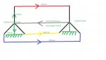
I would like to have your kind help regarding this dilemma i am facing about the unbalanced return current (in neutral in attached figure shown to be 50 Amp) for a three phases transformer and three phases loads. the question is: Is the path going to be path A or path B, and what i mean is the unbalanced current returning in neutral will go back to the transformer star point and get down into the ground connected at the star point of the transformer? or keep in circling between the transformer and phase A and transformer wont throw it in the ground? i made a small sketch just to make my self clear it shows what path A and B exactly are!!! Thank you!!!


I would like your help please any clues?


Best Regards all Sirs,
 

Attachments

  • Grounding.jpg
    Grounding.jpg
    12.1 KB · Views: 0

Besoeker

Senior Member
Location
UK
The unbalanced current in a 3-phase four wire system (A, B, C, N) would normally flow in the neutral.
The loads are connected between phase and neutral.
 

charlie b

Moderator
Staff member
Location
Lockport, IL
Occupation
Retired Electrical Engineer
The short answer to your question is that ?Path A? is not involved at all. Current does not flow into the ground (i.e., planet Earth) unless there is a fault somewhere in the system.

However, there are several things wrong with your sketch. First and foremost, you are incorrectly showing a connection between the current-carrying portion of the load and the ground. The ground wire at the load end is attached to the external metal portions of the load (e.g., the metal frame of a motor), not to any of the wires inside the component. If you disconnect the green wire from the load to the ground on the right side of your sketch, you will see that ?Path A? does not exist anymore, as should be the case.

Secondly, when current leaves the transformer along one of the phase conductors, it will return to the transformer on one or both of the other phase conductors. At any moment in time, the total amount of current flowing in the four wires (A, B, C, and N) is zero. But the way you are showing current flows, you have 350 amps flowing away from the transformer on A, B, and C, and you have 50 amps flowing back to the transformer on N. That is not how current flows.

Finally, you can?t add current in the three phases as though you were adding up the number of apples in one box to the number of apples in another box to come up with the total number of apples. The three currents do not reach their respective peak values at the same time, so you can?t add them up as though they were all the same type of quantity. To get the numerical value of the neutral current, therefore, you don?t add up A plus B plus C and assign whatever is leftover to N. This is the formula (with the symbology of A*2 meaning A squared):

N*2 = A*2 + B*2 + C*2 ?AB ? AC ? BC.
 

Besoeker

Senior Member
Location
UK
Finally, you can’t add current in the three phases as though you were adding up the number of apples in one box to the number of apples in another box to come up with the total number of apples. The three currents do not reach their respective peak values at the same time, so you can’t add them up as though they were all the same type of quantity. To get the numerical value of the neutral current, therefore, you don’t add up A plus B plus C and assign whatever is leftover to N. This is the formula (with the symbology of A*2 meaning A squared):

N*2 = A*2 + B*2 + C*2 –AB – AC – BC.

We've been here before. That formula works only if the power factor is identical for all three phases which is not the general case.
For example, if all three currents are equal it yields In = 0A

Here is what can happen if you have equal currents but differing power factors:

ThreephaseforTM01.jpg


Clearly In ≠ 0A even with balanced currents.

I've seen that formula posted a few times. I don't know why it is taught.
 
Last edited:

hisham1986

Member
Location
KSA/Riyadh.
what if the green grounding wire is disconnected

what if the green grounding wire is disconnected

Dear Charlie,

First i would like to thank you for this outstanding elaboration in explaining how it works,i really appreciate it,there might a small additional question i would like to know your answer for,well suppose we removed this green connection to ground on the load side and we made it only as a connection to the metal enclosure or cabinet of this load to the ground i.e:normal grounding to body of a fridge lets say, still the path would be path B right?
 

charlie b

Moderator
Staff member
Location
Lockport, IL
Occupation
Retired Electrical Engineer
Still the path would be B. However, when we connect a ground wire (green insulation, or bare copper) to the metal case of the motor (or the fridge), we do not connect the other end of the wire to the ground (i.e., into dirt, using a ground rod). Rather, the other end of the green wire is run alongside the black and white wires all the way back to the panel. The purpose of the green wire is to provide a low-resistance path for current to flow back to the source, in the event there is a failure inside the component (e.g., wire breaks free inside the motor, and touches the metal frame). That will cause a large current to flow (very briefly) in the green wire, a current so large that it will force the breaker to trip. When the breaker trips, the failure event is over, and it happens so fast that a person touching the motor frame when the failure occurred would not feel a shock.
 
T

T.M.Haja Sahib

Guest
hisham1986:
The path-A does exist! Remember parallel circuits: current in each is inversely proportional to the resistance (impedance) in each. Here the path-A is in parallel with the system neutral to load neutral path . The division of current between them is inversely proportional to the resistance or impedance in each of them. So the lower the earth resistance of neutral at system and load ends,greater is the flow of current via ground.
 

hisham1986

Member
Location
KSA/Riyadh.
Clarification please

Clarification please

Dear All gents,

It seems a bit confusing what i have received as info but to make my self more clear what i want to mainly know is the following:

DOES THE CURRENT RETURNING FROM THE LOAD( UNBALANCED CURRENT IN THE GREY COLORED LINE) ONCE IT REACHES THE STAR POINT OF THE TRANSFORMER GOES DOWN TO THE GROUND LOOP CONNECTED TO THE STAR POINT OF THE TRANSFORMER(PATH A) OR MAKES A CLOSED LOOP AND GOES BACK TO THE LOAD AGAIN (PATH B) AND FOMRS A CLOSED CIRCUIT CURRENT BETWEEN TRANSFORMER AND LOAD??


HOPE IT GETS MORE CLEAR AM SORRY IF ANYONE MISUNDERSTOOD ME THANK YOU ALL SIRS IN ADVANCE FOR YOUR HELP :)
 

hisham1986

Member
Location
KSA/Riyadh.
N.B

N.B

AM SORRY JUST FOR CLARIFICATION: THE GROUNDING CONNECTION AT THE LOAD (GREEN COLOR) IS INTENDED TO BE CONNECTED TO THE BODY OF THE LOAD AND NOT TO THE NEUTRAL POINT OF THE LOAD ITSELF!!

THANKS AGAIN
 

charlie b

Moderator
Staff member
Location
Lockport, IL
Occupation
Retired Electrical Engineer
The path-A does exist!
No it doesn't. It would, as shown on the sketch. But the OP has clarified that the sketch has an error, in that the green wire at the load is intended to be connected to the external case, not to the current-carrying wires.
 

charlie b

Moderator
Staff member
Location
Lockport, IL
Occupation
Retired Electrical Engineer
First, let me ask you not to type using ALL CAPITAL LETTERS. It makes the post harder to read, and is considered equivalent to SHOUTING AT US.
DOES THE CURRENT RETURNING FROM THE LOAD (UNBALANCED CURRENT IN THE GREY COLORED LINE) ONCE IT REACHES THE STAR POINT OF THE TRANSFORMER GOES DOWN TO THE GROUND LOOP CONNECTED TO THE STAR POINT OF THE TRANSFORMER(PATH A)
No.
. . . OR MAKES A CLOSED LOOP AND GOES BACK TO THE LOAD AGAIN (PATH B) AND FORMS A CLOSED CIRCUIT CURRENT BETWEEN TRANSFORMER AND LOAD??
Yes. Once current has returned to the star point of the transformer, it is pushed once again through the transformer windings, and sent back towards the load. There is no driving force that would push the current into the dirt.
Dear All gents,
Please be advised that we have ladies participating in the forum as well.


Besoeker

Senior Member
Location
UK
hisham1986:
The path-A does exist! Remember parallel circuits: current in each is inversely proportional to the resistance (impedance) in each. Here the path-A is in parallel with the system neutral to load neutral path .
If the neutral is earthed at the supply transformer end isn't that path A? Not in parallel with anything?
What's less likely to exist is the neutral to earth connection at the load end.
 

hisham1986

Member
Location
KSA/Riyadh.
Thank you.

Thank you.

Dear All,

I apologize for writing in capital letters i dont mean to shout at anyone for sure and didnt have this intention either :) excuse me again for that ,on the contrary i appreciate your help and respect your experience too.

And as for the word "Gents" i said it only because men were contributing in this thread :) but thank you charlie b for your gentle note.


Best regards.
 
T

T.M.Haja Sahib

Guest
THE GROUNDING CONNECTION AT THE LOAD (GREEN COLOR) IS INTENDED TO BE CONNECTED TO THE BODY OF THE LOAD AND NOT TO THE NEUTRAL POINT OF THE LOAD ITSELF!!


Even though the grounding connection at the load (green color) is connected to the body of the load, the neutral wire from the load is bonded to the ground at the service equipment of the load ( if your electrical installation is covered by NEC) and so the parallel path of ground and so the current through it can not be avoided for unbalanced three phase loads.

So I am afraid there may be error in

No it doesn't. It would, as shown on the sketch. But the OP has clarified that the sketch has an error, in that the green wire at the load is intended to be connected to the external case, not to the current-carrying wires.
 
T

T.M.Haja Sahib

Guest
hisham1986:
Does the transformer you mentioned in the OP belong to the utility or is it customer owned?
 

david luchini

Moderator
Staff member
Location
Connecticut
Occupation
Engineer
Even though the grounding connection at the load (green color) is connected to the body of the load, the neutral wire from the load is bonded to the ground at the service equipment of the load ( if your electrical installation is covered by NEC) and so the parallel path of ground and so the current through it can not be avoided for unbalanced three phase loads.

This is incorrect. You yourself point out that the neutral is bonded to ground ONLY at the service equipment end. To create a parallel path, the neutral would have to be bonded at the service end, and at the load. The NEC prohibits this.
 

kwired

Electron manager
Location
NE Nebraska
If the neutral is earthed at the supply transformer end isn't that path A? Not in parallel with anything?
What's less likely to exist is the neutral to earth connection at the load end.

hisham1986:
Does the transformer you mentioned in the OP belong to the utility or is it customer owned?

If the transformer in the drawing is a utility transformer there will be grounding electrode at the transformer, if the load on the right represents the service equipment, or at least assumes there is service equipment somewhere between the source and the load then there is another grounding electrode at the service equipment. There is an "earth parallel" between the source and the service equipment if there is a grounding electrode at each.
 

Besoeker

Senior Member
Location
UK
There is an "earth parallel" between the source and the service equipment if there is a grounding electrode at each.
I agree. I have just not come across any installation where there was a grounding electrode at the load end. As I posted in another thread, a separate grounding conductor, grounded at the supply transformer is run for most of the systems I've seen here.
 

kwired

Electron manager
Location
NE Nebraska
I agree. I have just not come across any installation where there was a grounding electrode at the load end. As I posted in another thread, a separate grounding conductor, grounded at the supply transformer is run for most of the systems I've seen here.

Some of us are reading into this too hard or the OP was not clear enough with the drawing. As I said if the transformer was a utility transformer, the utility will ground at the transformer, there will be a service before the load, NEC requires us to provide a grounding electrode system at the service. So there is an earth parallel between the source and the service, but I'm guessing that that was not really a concern of the OP, and was kind of overlooked. He would need to draw the service in between the source and the load in his drawing.

I think his real concern is how much current does the neutral carry with the ungrounded conductors loaded as stated and assume there is no parallel neutral path issues.
 
Last edited:
T

T.M.Haja Sahib

Guest
I agree. I have just not come across any installation where there was a grounding electrode at the load end.
You are not in US and that is perhaps why you have just not come across any installation where there was a grounding electrode at the load end. :)
 
Status
Not open for further replies.
Top