timm333
Senior Member
- Location
- Minneapolis, MN
- Occupation
- Electrical Design Engineer
I previously did high voltage underground cable calculations based on IEC 60287 using excel spreadsheet. Now I need to do the low voltage underground cable calculations based on NEC; I have few questions. Thanks for help.
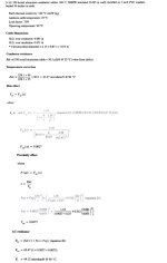
1. Is it advisable to completely ignore the tables of NEC, and do calculations based on Neher McGrath method?
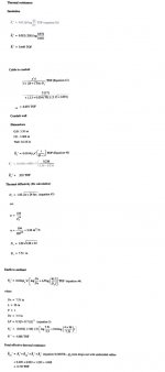
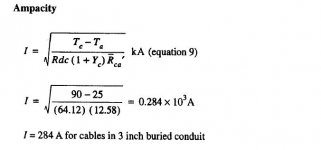
2. Is it possible to do the hand calculations of Neher McGrath method?
3. Some part of cable length is direct buried, and some is in duct bank. As there would be more heat loss in duct bank, so can we ignore the direct buried part, and do the calculations by assuming that the whole cable length is in duct bank?
1. Is it advisable to completely ignore the tables of NEC, and do calculations based on Neher McGrath method?
2. Is it possible to do the hand calculations of Neher McGrath method?
3. Some part of cable length is direct buried, and some is in duct bank. As there would be more heat loss in duct bank, so can we ignore the direct buried part, and do the calculations by assuming that the whole cable length is in duct bank?