johnsciolino
Member
- Location
- Jacksonville, Fl
I'm looking for some straight answers why you would use a 100% rated Main Breaker in a service.
There's an example in the Annex of the code book that calculates the following:
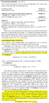
Continuous load 56,600va
NonContinuous load 42,400va
25% of continuous 14,200va
Total 113,200va
113,200/(480*1.732)= 136amp
It says to select the next size breaker of 150amps or use a 125amp 100% rated breaker.
Does the feeder come into play when using this exception? 240.42 A(1) Exception No. 2
This is from a friend of mine, i think we are talking about the same thing but it seems he is selecting the 100% rating based on the conductor size.
He is saying I can terminate four sets of 600mcm in a 2000amp breaker with 80% rating or a 1600amp breaker at 100% rating. I can't find any examples of this in the code book or other references to the 100% breaker rating. This is for the service feeder to the main.
So, for the purposes of this discussion, let’s assume the load has been calculated per 230.42 (2) and this has resulted in a size of 1,560 amps. My view is as follows:
-------------------------------------
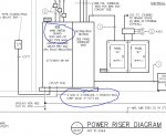
In a recent plan, we have a 1000amp Main Breaker Service panel
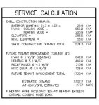
Load calc is 270,200va or 750.6amps
Feeder shown is 3 sets of 4-600mcm copper in a 3-1/2" PVC pipe underground 475a x 3=1425amp 1425 X .8=1140amps (assuming the neutral is non-linear)
75 degree column says 420a X 3=1260amps (this is what the breaker lugs are good for)
I am being told that this Main Breaker needs to be rated 100% by the reasoning above. I believe the wire is a separate issue from selecting a 100% rated breaker.
Technically, I think we could use 3 sets of 4-500mcm on a standard 1000a breaker based on the load calculation and the wire size since the calculation is taking into account continuous and non-continuous loads. The way the code reads, technically, I think we could use an 600amp 100% rated main in lieu of a 1000amp, the wire would be part of that assembly and calculated on the continuous and non-continuous load only (750.6 amps). Based on the calculation, I think you could also use a standard 800amp Main breaker with the same wire size. Am I wrong in this thinking?
There's an example in the Annex of the code book that calculates the following:
Continuous load 56,600va
NonContinuous load 42,400va
25% of continuous 14,200va
Total 113,200va
113,200/(480*1.732)= 136amp
It says to select the next size breaker of 150amps or use a 125amp 100% rated breaker.
Does the feeder come into play when using this exception? 240.42 A(1) Exception No. 2
This is from a friend of mine, i think we are talking about the same thing but it seems he is selecting the 100% rating based on the conductor size.
He is saying I can terminate four sets of 600mcm in a 2000amp breaker with 80% rating or a 1600amp breaker at 100% rating. I can't find any examples of this in the code book or other references to the 100% breaker rating. This is for the service feeder to the main.
So, for the purposes of this discussion, let’s assume the load has been calculated per 230.42 (2) and this has resulted in a size of 1,560 amps. My view is as follows:
- The service entrance conductors must be rated to carry not less than 1,560 amps.
- The main breaker must be rated for a current not less than 1600 amps since it is the closet size breaker setting above the calculated load (it could be higher but that’s irrelevant)
- Based on the capacities listed in 310.15, the most efficient combination of conductors which meet this criteria would be for sets of 4-#600kcmiil since this equals 1600A. Incidentally, four sets of 500kcmil would not comply.
- I have the option of terminating these conductors in breaker which is listed at 100% of it’s trip setting.
- I have the option of terminating these conductors in a 2,000A breaker which is rated at 80% trip setting.
-------------------------------------
In a recent plan, we have a 1000amp Main Breaker Service panel
Load calc is 270,200va or 750.6amps
Feeder shown is 3 sets of 4-600mcm copper in a 3-1/2" PVC pipe underground 475a x 3=1425amp 1425 X .8=1140amps (assuming the neutral is non-linear)
75 degree column says 420a X 3=1260amps (this is what the breaker lugs are good for)
I am being told that this Main Breaker needs to be rated 100% by the reasoning above. I believe the wire is a separate issue from selecting a 100% rated breaker.
Technically, I think we could use 3 sets of 4-500mcm on a standard 1000a breaker based on the load calculation and the wire size since the calculation is taking into account continuous and non-continuous loads. The way the code reads, technically, I think we could use an 600amp 100% rated main in lieu of a 1000amp, the wire would be part of that assembly and calculated on the continuous and non-continuous load only (750.6 amps). Based on the calculation, I think you could also use a standard 800amp Main breaker with the same wire size. Am I wrong in this thinking?