BandGap1.1eV
Member
- Location
- East Coast
I need someone better versed in electrical theory to chime in.
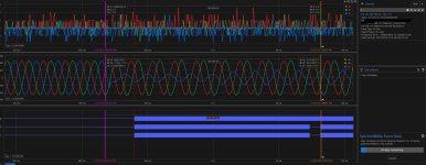
I've got an 840 kVA behind the meter PV system that is experiencing over-voltage failures at the AC contactors in the inverters. Five of the seven inverters on site have experienced the same failure mode, in additional to many of the lighting drivers in other parts of the building. We have SEL waveforms of the utility voltage showing multiple Phase to Ground faults on the utility circuit since mid-February. I'm a bit of a dullard when it comes to the theory, so I'm wondering if anyone here could diagram/explain how a ground fault on the 13.8 kV side of a tranformer can induce an overvoltage on the secondary.
Thoughts?