UTILITY TRANSFORMER DAMAGE CURVES

Status
Not open for further replies.

PE (always learning)

Senior Member
Location
Saint Louis
Occupation
Professional Engineer
Hey everyone,

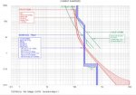
So I have a question in regards to transformer damage curves and how to optimize protection between the utility primary fuse and the main circuit breaker on the secondary side. My utility transformer is 750 kVA and my main size is 3000 amps. I know the transformer size seems oddly low for a 3000 amp main, but the utility has sized the transformer based on the demand load. My question is, what would be my optimal settings for the secondary 3000 amp main breaker in order to protect the transformer? I don't think I will be able to put any practical settings to protect the transformer from thermal overload on the secondary because the breaker is too large. In this case would my primary fuse be doing all the protection? I have attached a TCC of this scenario for your reference.

Best Regards,
Eric Fiedler
 

Attachments

  • SERVICE ENTRANCE TCC.jpg
    SERVICE ENTRANCE TCC.jpg
    21.2 KB · Views: 11

iceworm

Curmudgeon still using printed IEEE Color Books
Location
North of the 65 parallel
Occupation
EE (Field - as little design as possible)
making wildly inaccurate guesses (cause mivey is correct, the TCC is pretty fuzzy)

Primary is 12,470V, 35A
Primary fuse is 100A,

Secondary is 480V, 900A FLA

If the 3000A secondary main is adjustable, turn it down to 40%. That would give 1200A. pretty close to 125% of the xfm FLA ( 1.25 x 902A = 1128A)

1200A will show up as 46A reflected to the 12,470V base.

The primary fuse is selected for ~3X FLA. Which is about where utilities like it. It doesn't stop the customer from overloading the xfm, but it will put out the fire - eventually, maybe. So, no, the primary fuse is not protecting the transformer.

the worm
 

iceworm

Curmudgeon still using printed IEEE Color Books
Location
North of the 65 parallel
Occupation
EE (Field - as little design as possible)
Look at the bottom portion of the image. It's 12,470V!
Secondary voltage would be the concern.
I'm guessing 480V, since that gets the numbers to match up with a 12,470V base.

But then again -......

Maybe that is just a worm's-eye-view:roll:
 

topgone

Senior Member
Secondary voltage would be the concern.
I'm guessing 480V, since that gets the numbers to match up with a 12,470V base.

But then again -......

Maybe that is just a worm's-eye-view:roll:

Nope. The secondary breaker is a 3000A as the OP said. I guess it's 120V(FLA=3,608A).
 

don_resqcapt19

Moderator
Staff member
Location
Illinois
Occupation
retired electrician
This just appears to be the typical mismatch between the service size required by the NEC load calculations and what equipment the utility uses to supply that service. You don't worry about protecting the utility side. If the NEC load calculation requires a 3000 amp service, that is what your service equipment must be rated at. You can't reduce that.
 

wbdvt

Senior Member
Location
Rutland, VT, USA
Occupation
Electrical Engineer, PE
Your secondary protective device is not going to protect the transformer from any transformer internal faults or faults in the secondary conductors. The secondary may prevent a transformer overload but I think you would other issues if that is the case.

Adjusting the main breaker settings to coordinate with the utility transformer primary fuse will most likely cause coordination issues with in your system. I have seen many systems designed and built to serve larger loads than they are presently doing and the utility has sized it's transformer for the existing loads not possible loading. This leads to the issue you are seeing.

The area of mis-coordination is in the overload region which should not be a concern for a main breaker unless you have added significant loads and have not discussed this with the utility.
 

kingpb

Senior Member
Location
SE USA as far as you can go
Occupation
Engineer, Registered
My utility transformer is 750 kVA and my main size is 3000 amps. I know the transformer size seems oddly low for a 3000 amp main, but the utility has sized the transformer based on the demand load.

You are not going to be able to coordinate; if utility has provided a smaller transformer (very typical). It is their transformer, they will provide protection for it.
 

topgone

Senior Member
Your secondary protective device is not going to protect the transformer from any transformer internal faults or faults in the secondary conductors. The secondary may prevent a transformer overload but I think you would other issues if that is the case.

Adjusting the main breaker settings to coordinate with the utility transformer primary fuse will most likely cause coordination issues with in your system. I have seen many systems designed and built to serve larger loads than they are presently doing and the utility has sized it's transformer for the existing loads not possible loading. This leads to the issue you are seeing.

The area of mis-coordination is in the overload region which should not be a concern for a main breaker unless you have added significant loads and have not discussed this with the utility.

No need to coordinate the primary and the secondary breakers there. They serve the same load! Either one tripping, you still lose the power to your loads, IMHO.
 

PE (always learning)

Senior Member
Location
Saint Louis
Occupation
Professional Engineer
Your secondary protective device is not going to protect the transformer from any transformer internal faults or faults in the secondary conductors. The secondary may prevent a transformer overload but I think you would other issues if that is the case.

Adjusting the main breaker settings to coordinate with the utility transformer primary fuse will most likely cause coordination issues with in your system. I have seen many systems designed and built to serve larger loads than they are presently doing and the utility has sized it's transformer for the existing loads not possible loading. This leads to the issue you are seeing.

The area of mis-coordination is in the overload region which should not be a concern for a main breaker unless you have added significant loads and have not discussed this with the utility.

Agreed, there is no way I would be able to get my 3000 amp main to coordinate with the transformer damage curve on this one. As you said, doing this would cause other coordination issues within the system and I do agree with you on the fact that there is no way we are ever going to overload the main unless they throw on a lot of future load. What I am somewhat concerned with is if the utility fuse will coordinate with anything down stream of the 3000 amp main breaker. The utility did not provide me with any information beyond the fact that we are using a SM-20 fuse at 12470 volts and it is being fed out of S&C pad mounted PME switchgear so I made an assumption on the utility fuse size and went with 50 amps for a 750 KVA transformer.
 
Last edited:

mivey

Senior Member
Agreed, there is no way I would be able to get my 3000 amp main to coordinate with the transformer damage curve on this one. As you said, doing this would cause other coordination issues within the system and I do agree with you on the fact that there is no way we are ever going to overload the main unless they throw on a lot of future load. What I am somewhat concerned with is if the utility fuse will coordinate with anything down stream of the 3000 amp main breaker. The utility did not provide me with any information beyond the fact that we are using a SM-20 fuse at 12470 volts and it is being fed out of S&C pad mounted PME switchgear so I made an assumption on the utility fuse size and went with 50 amps for a 750 KVA transformer.
Maybe they meant an SM-4 with a 20 amp rating.

However, SMU-20 or SM-4, I would think they might use a 30 amp fuse, maybe a 40 amp at the most.
 

topgone

Senior Member
Agreed, there is no way I would be able to get my 3000 amp main to coordinate with the transformer damage curve on this one. As you said, doing this would cause other coordination issues within the system and I do agree with you on the fact that there is no way we are ever going to overload the main unless they throw on a lot of future load. What I am somewhat concerned with is if the utility fuse will coordinate with anything down stream of the 3000 amp main breaker. The utility did not provide me with any information beyond the fact that we are using a SM-20 fuse at 12470 volts and it is being fed out of S&C pad mounted PME switchgear so I made an assumption on the utility fuse size and went with 50 amps for a 750 KVA transformer.
SM-20 fuse rated 50A will melt in about 100A. A fusing factor is about 100/34= 2.9!
 

mivey

Senior Member
SM-20 fuse rated 50A will melt in about 100A. A fusing factor is about 100/34= 2.9!
and the transformer would not last very long.

Fusing for cold load pick up of about 200% is normal in most cases. I doubt 300% would be a standard practice, for a 750 kVA anyway. You might be okay risking a smaller, cheaper transformer if you had a good reason.
 

wbdvt

Senior Member
Location
Rutland, VT, USA
Occupation
Electrical Engineer, PE
One reason to coordinate the main bkr with the utility fuse is to aid in troubleshooting. If the fuse goes, then the issue could be the transformer or secondary cable if coordinated. If not the fuse could be blowing on an issue downstream of the secondary.

The utility should be able to tell you the fuse size for certain. If they said SMU-20, that would be a fuse size but saying SM-20 that could referring to the fuse holder SMD-20.

The utility I used to work for would use either a 140T or 100T cutout fusing, depending on mainline fusing, for a 12.5kV 500kVA padmount. This would be in conjunction with transformer bayonet CLF C12 fusing.

Cooper's Distribution Book has either a 50A or 80A fusing for a 12.5kV 500kVA padmount.

The SMU-20 seems a little small. Some utilities will put the fuse size on the riser pole.
 

mivey

Senior Member
The utility should be able to tell you the fuse size for certain. If they said SMU-20, that would be a fuse size but saying SM-20 that could referring to the fuse holder SMD-20.
No. The SMD is the fuse assembly. The SMU-20 is a fuse cartridge that fits in the holder that comes in a range of sizes.

The utility I used to work for would use either a 140T or 100T cutout fusing, depending on mainline fusing, for a 12.5kV 500kVA padmount. This would be in conjunction with transformer bayonet CLF C12 fusing.
Different fuses are usually 150% or 200% rated so it matters what type fuse you are using.

The SMU fuses are 200% rated.
 

wbdvt

Senior Member
Location
Rutland, VT, USA
Occupation
Electrical Engineer, PE
No. The SMD is the fuse assembly. The SMU-20 is a fuse cartridge that fits in the holder that comes in a range of sizes.

I wasn't clear on the point I was trying to make. I am aware of the difference between SMD & SMU. However, the OP stated the utility just said SM-20 and the OP assumed that meant a 20A fuse. Without the D or U indicated, that assumption cannot be made.

And my comment on fuse sizes was meant to illustrate that utilities usually have a book of standards they use for construction and fusing. The utility should be able to refer to that if they do not have the fuse size in their records or system model.
 

mivey

Senior Member
I wasn't clear on the point I was trying to make. I am aware of the difference between SMD & SMU. However, the OP stated the utility just said SM-20 and the OP assumed that meant a 20A fuse. Without the D or U indicated, that assumption cannot be made.

And my comment on fuse sizes was meant to illustrate that utilities usually have a book of standards they use for construction and fusing. The utility should be able to refer to that if they do not have the fuse size in their records or system model.
The OP assumed a 50 amp fuse. I just wondered if they meant a 20 amp fuse and the OP got the wrong info. 50 amp seems a little big to me.
 
Status
Not open for further replies.
Top